Centerline overshoots vary from one drafting standard to another.
Additionally, some sizes of holes require overshoots to be proportional to their diameters. Hence, when you draw centerlines in the Content Editor, you must configure overshoots such that AutoCAD Mechanical toolset dynamically controls its length at insertion time.
To let AutoCAD Mechanical toolset control overshoot length, you must dimensionally constrain the overshoot with a variable named OVERSHOOT. At insertion time AutoCAD Mechanical toolset dynamically assigns values to OVERSHOOT. The workflow described below shows how the slot in the illustration was constrained.
| Task | Comments | |
| 1. | Create a User Parameter named OVERSHOOT in the Parameters Manager | You use this variable to constrain the overshoot, later on. |
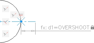
| 2. | Use the POINT command to insert a point at the intersection of the circle and centerline. | You use the point to enable object snap assist you position dimensional constraints precisely. |
| 3. | Geometrically constrain the geometry, including the point | Constraining the point ensures that the points stay fixed and the overshoot extends out. |
| 4. | Apply dimensional constraints to the overshoot and assign it to the OVERSHOOT variable | When inserted in the drawing area, AutoCAD Mechanical toolset assigns values to the OVERSHOOT variable, depending on the standard and the diameter of the hole. |