The  AutoTouchTrigger probing methods are designed for use with touch trigger probes. The probing methods available for use depend on the type of inspection item you are working with and the probe you selected in the Machine tab. For example, helical methods are available for cones and cylinders, but not for arcs.
Helical — Helical generates a probe path that winds around the feature from top to bottom, or from bottom to top. The probe path can be calculated using Points, Pitch, or Chordal values.
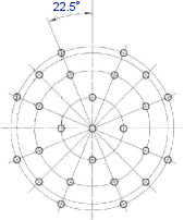
ISO10360Probing — This method checks the probe calibration on a sphere, in accordance with ISO 10360. It creates a probe path on the upper hemisphere, with 25 points in 4 slices (3 slices of 8 points and 1 slice of a single point on the top of the sphere).
The calibration is not transferred back from the machine to the controller.
Longitudinal — This method generates a probe path containing a series of linear passes (segments) parallel to the feature axis. The probe path can be calculated using Points, Pitch, or Chordal values.
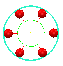
Optimal — This method generates a probe path containing a fixed number of slices around the feature with each slice having a fixed number of evenly distributed points. The numbers of points and slices depend on the feature type. For example, the default probe path of a circle is six points in a single slice:
For planes, lines, and inspections groups where you specify the points to be probed, the method adds a clearance distance (equal to the Safe Height value) to the start and end of the probe path.
Raster — This method creates a raster pattern of probe points. To change how a raster probe path is calculated, use the Raster Parameters dialog.
SelectedSurface — This method creates a raster pattern for a specified surface. To select the surface and customize the probe path, use the Surface Parameters dialog.
Slices — This method generates a probe path of slices around a feature. The slices can be calculated using Points, Pitch, or Chordal values. The BodyPanel method is a special SlicesPoints method that creates a reference plane and assigns it to each new 2D feature. This is useful when inspecting parts, such as body panels.
SlotEndOnly — For a slot, this method generates a probe path with slices that have points evenly distributed at each end.
SlotRectangleMin — For a slot or rectangle, this method generates a probe path with rectangular slices defined by the minimum number of points.
StylusVectorSafe — This method generates a probe path that retracts the Retract distance along the surface normal, and then retracts the Safe height distance along the probe vector. Use it when you want to probe a feature on an inclined or vertical plane and an obstruction prevents the probe from retracting along the surface normal.
SurfaceEdgeProbing — This method creates a probe path for a Guided Edge Point group. The path alternates between probing surface and edge points.
SurfaceSurfaceProbing — This method creates a probe path for a Guided Edge Points group. The path probes all the surface points before probing the corresponding edge points.
ZAxisSafe — This method generates a probe path that retracts the Retract distance along the surface normal, and then retracts the Safe height distance in the machine's Z axis. Use it when you want to probe a feature on an inclined or vertical plane and an obstruction prevents the probe from retracting along the surface normal.
Fallback — This method replaces the original method with one that works in the current configuration. Because the replacement method may not be optimal, you should select another method before playing the inspection sequence. You cannot select Fallback. It is used only when the original method cannot be used with the currently selected probe, or when the item was specified on a different version of PowerInspect using a probing method that is unavailable in this version.
The 5Axis equivalents of these methods create 5-axis moves between touch points. If your measuring device does not support 5-axis moves, these options are treated as 3-axis methods.