Specify and manage the probes you want to use for the inspection.
To select a probe tool
- In the Machine tab, click the Probe tool area.
- In the
Probe list, select the probe.
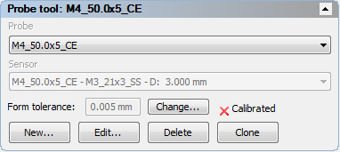
If you want to create a probe from an existing probe assembly, select the assembly and click Clone.
- If more than one sensor is available on the selected probe, select the sensor you want to use from the Sensor list.
- To change the calibration tolerance for the selected probe or sensor, click
Change.
Note: The Form tolerance and Change button are displayed only when the document is connected to the measuring device, and Use form tolerance setting is selected in the Calibration Settings dialog.
To create a probe tool assembly
If you want to specify a star probe, first select the Show probe tool connections check box in the Options dialog.
- In the Machine tab, click the Probe tool area.
- Click New. The Probe Tool Assembly dialog is displayed.
- Enter a name for the probe tool assembly in the
Probe tool assembly box.
Note: If you are using the I++ protocol to connect to the measuring device, use the same name for the probe tool assembly as that used in the I++ Server. This enables PowerInspect to synchronize probe tools with the server when you connect the document to the measuring device. When PowerInspect is connected to the I++ Server, the name of the active tool is displayed in PowerInspect's status bar.
- In the Available probe tool parts area, select the type of part you want to add to the probe tool assembly. The list displays all the parts available in the probe database.
- Choose the part you want to add:
- If the part is in the Available probe tool parts list, double-click its entry to add it to the probe tool assembly.
- If the part is not in the Available probe tool parts list, click Create custom part to enter its details.
The part is added to the Probe tool assembly list, and the insertion line moves to show where the next part will be inserted. To change the insertion position, double-click a part in the list to reposition the insertion line after it.
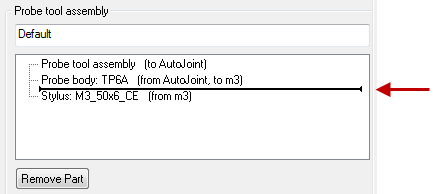
- Continue inserting parts until the probe tool assembly is complete.
Note: To remove a part from the assembly, select its entry in the Probe tool assembly list, then click Remove Part.
- Click Save to save your changes and close the dialog. The assembly is selected as the current probe tool and displayed in the CAD view.
To view or edit a probe tool assembly
- In the Machine tab, click the Probe tool area.
- Select the probe tool assembly in the Probe list.
- Click
Edit. The
Probe Tool Assembly dialog is displayed:
- To rename the probe tool assembly, type a new name in the area at the top of the dialog.
- To delete a part from the probe tool assembly, select its entry in the Probe tool assembly list and click Remove Part.
- To add a part to the assembly: move the insertion point in the Probe tool assembly list to the position where you want to add the part; select the type of part you want to add in the Available probe parts list; and double-click the part you want to add in the Available probe parts list.
- Click Save to save your changes and close the dialog. The assembly is selected as the current probe tool and displayed in the CAD view.
To delete a probe tool assembly
- In the Machine tab, click the Probe tool area.
- Select the probe tool assembly you want to delete in the Probe list.
- Click
Delete.
The probe tool assembly is deleted from the document. Only the probe tool assembly is deleted; the components making up the assembly remain available for use in other assemblies.