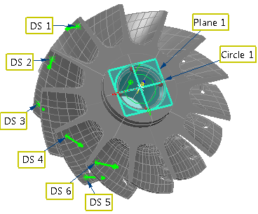
When you can lock only some of the axes of a part with geometric items, you can create an RPS alignment using a mixture of geometric items and guided inspection points. The geometric items are used to lock selected axes, and the points are then used to create the remaining constraints. The following example shows how to create an RPS alignment using a circle and inspection points positioned around the blades of an impeller.
To create an RPS alignment using surface inspection points:
- Create the geometric features required for the alignment.
- Create a surface inspection group containing the guided surface points.Note: Guided surface points are available only when creating inspections for CNC and Manual machines.
- Click Hometab > Create panel > Alignment > RPS Alignment to display the RPS Alignment Definition dialog, and enter a Name for the alignment.
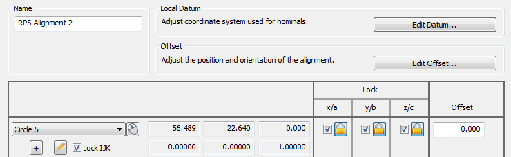
- Select the geometric items you want to use for the alignment. In the following example, three translation axes and two rotational axes are locked by Circle 1 because the whole feature is used and Lock IJK is selected,
- Select the inspection points you want to use for the alignment. For example:
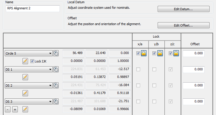
The Lock column displays the normal of each point.
- When you have added all the inspection points you want to use, click OK to close the dialog and create the alignment.
- Measure the features. PowerInspect optimizes the alignment to create a best fit and reports the standard deviation of the measurements in the RPS Alignment Definition dialog, and in the Info and Report tabs.