The RPS alignment enables you to align a part to the CAD model by using a set of features to constrain the part's axes of rotation and translation. With it, you can:
- lock a part in six axes and create a perfectly constrained alignment.
- constrain rotations by aligning them with the axis of a feature, such as a plane or a whole circle.
- create mixed alignments combining geometric features and guided surface points.
To create an RPS alignment:
- Select the Definition level in the inspection sequence.
- Click Home > Create panel > Alignment arrow > RPS Alignment. The RPS Alignment Definition dialog is displayed.
If you have a drawing with nominal values in a transformed coordinate system, but no CAD model, you can create an alignment by clicking Edit Datum on the Parameters tab, and applying a transformation to the values.
- Enter a Name for the alignment.
- By default, the nominals of the alignment features are reported relative to the PCS (CAD Datum). To view or edit the nominals relative to another datum, click Edit Datum on the Parameters tab and specify the translation and rotation of the datum using the Transformation Matrix dialog.
- On the Constraints tab, select a feature from the left drop-down list, or click
 and select the feature in the CAD view. If you select a:
 - point, select one or more check boxes in the Lock column to specify which axes are constrained by the feature. For example:
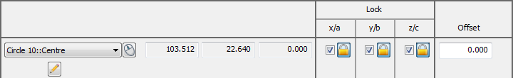
When you over-constrain an axis, PowerInspect creates a best-fit of all the features. Click
 next to the check box to exclude the axis from the best-fit calculation. The button changes to
  .
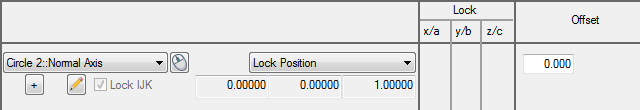
. - line, axis, or vector, select an option from the right drop-down list. Select:
Lock Position to use the feature to constrain the position and translation axes.
Lock Direction to constrain only the rotation axes. For example:
- point, select one or more check boxes in the Lock column to specify which axes are constrained by the feature. For example:
- To change the nominals of the selected item, click
 and enter the new values in the item dialog.
 - To position the item for the purposes of this alignment, enter the distance by which you want to offset the item along the normal in the Offset box. The offset is applied to the item and any Offset/Thickness value specified in the item dialog.
You can enter an offset only when the selected item allows it. For example, you can enter an offset for a probed circle, but not for a probed plane.
- Click
 to define the next feature.
 - Repeat steps 5 to 8 to specify the other features with which you want to create the alignment. For example:
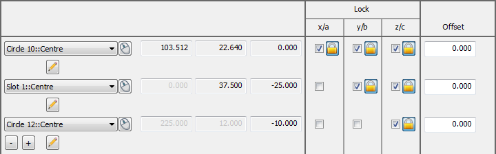
Axes can be locked in any arrangement; you can specify up to 100 constraining items. If the alignment is over-constrained, PowerInspect creates the best-fit of the items you specified to include in the optimization, and reports their standard deviations in the alignment dialog, and in the Report tab.
- If the inspection sequence contains constructed features that use measurements taken by different measuring devices or from different device positions, select the Use transformed data check box. This converts the device coordinates to CAD coordinates so that all calculations use a common reference system.
The check box has no effect when all coordinates in the inspection are collected with one measuring device in one position, or when the inspection sequence contains no constructed features.
- To apply an offset to the alignment, click Edit Offset on the Parameters tab, and enter the offset in the Transformation Matrix dialog.
- If one or more of the features used in the alignment are measured using a point cloud, select the alignment used to calculate the measured values of the point cloud in the Reference alignment list.
- To include the details of the alignment in the report, select the Output in report check box.
- Click OK to save your changes and close the dialog.