Automatic orientation positions the measuring device so that the probe is normal to the feature to be measured. Use it when you do not want to specify the probe orientation with which a feature is to be measured.
For example, to set the automatic orientation for an inspection group:
- Select the Sequence Tree tab.
- Select the Features tab.
- In the inspection sequence, select the inspection group.
- Click the Edit
 button to edit the item's settings.
 - Click the Auto-Orientation
 button.
 - In the Probing method list, select the UserDefined probing method of Optimal.
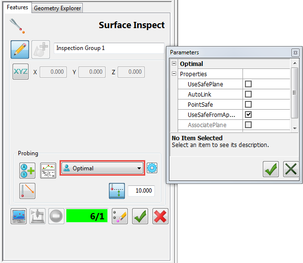
- Click the Use probe safe parameter
 button to specify the safe height to be used when measuring the feature. For an Optimal method, this sets the approach distance before the first probed position, and the retract distance after the last probed position.
 - Click the Parameters
 button to view the parameters that determine the probe path for the selected probing method, then close the Parameters dialog.
Only advanced users should change the probing parameters. If the standard probing methods included with PowerInspect do not meet your needs, contact Technical Support to discuss your requirements.
- Click the Save geometric feature
 button to save your changes.
Note: For geometric item or surface inspection groups, click the Details  button on the Features tab to view the positioning moves in the probe path.
button on the Features tab to view the positioning moves in the probe path.