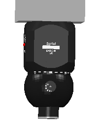
Select and calibrate the head with which you want to perform the inspection.
Note: The
Probe head
area is available only when creating inspections for CNC and Manual machines. To specify the probe details for OMV inspections, use the
Probe
area.
- For a CNC machine:
- In the Machine tab, click the Probe head area.
- Select a probe head from the list. If the head you want to use is not shown, click Create.
The head is displayed in the CAD view.

If the head is not shown, click to display it.
- If the head in the CAD view is not aligned with the head of the measuring device, use the
RX,
RY, and
RZ boxes to rotate the on-screen head to the same orientation as the device head.
For example, if the LED of the device head is orientated along the X axis, and the LED in the CAD view is orientated along the Y axis, you can align the heads by using the RZ box to rotate the on-screen head to 90 degrees.
- For a manual CMM:
- In the Probe Tool area, specify a probe for the inspection.
- Connect to the measuring device. The calibration status of the head is displayed in the Probe View.
- In the
Probe head area click
Calibrate to calibrate the head. If you selected:
- Full in the
Calibration
page of the
Options dialog, the
Probe Head Calibration wizard is displayed.
Follow the instructions in the wizard to calibrate the probe head.
- Simple in the
Calibration
page of the
Options dialog, the
Probe Head Mounting Direction dialog is displayed.
Enter the orientation of the probe assembly with its axis normal to the mounting face of the probe head.
- Full in the
Calibration
page of the
Options dialog, the
Probe Head Calibration wizard is displayed.