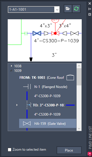
You can choose valves, fittings, and inline instruments from the P&ID Line List and place mapped Plant 3D counterparts in the model.
Valves, fittings, and inline instruments are listed under each line group.
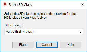
If a P&ID object is mapped to more than one Plant 3D object, you can specify the Plant object when you place it in your drawing.
- Open a Plant 3D model.
- On the ribbon, click Home
 Part Insertion panel
  P&ID Line List.
- In the P&ID Line List window, do the following:
- In the drop-down list, click the P&ID drawing whose lines and components you want to view.
- In the tree view, expand the Pipe Line Group. Click an item (for example: Gate Valve).
- Click Place.
 Note: Placing unmapped items display the Custom Parts dialog box. You can follow the steps in the dialog box to build custom parts.
 - Do one of the following:
- If the size and spec match, go to step 5.
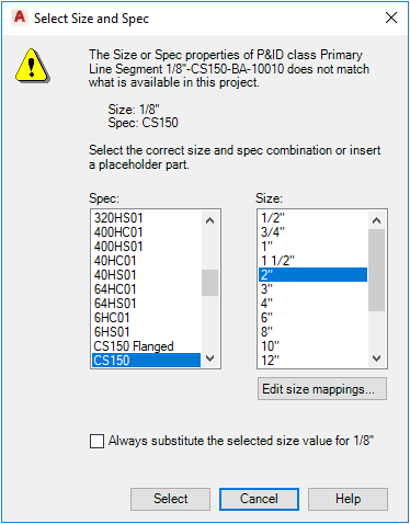
- If the size or spec do not match, in the Select Size and Spec dialog box, do the following:
- Under Spec, click a spec (for example: CS150).
- Under Size, click a size (for example: 4”).
- If you are sure that your choice is accurate for all situations, select the check box labeled Always Substitute the Selected Size For [size]. (The spec is not saved along with the size.)
- If the size you want is not available, click Edit Size Mappings to edit the default mapping file.
- Click Select.

- Do one of the following:
- If the P&ID object class is mapped to a single Plant 3D class, go step 6.
- If the P&ID object class is mapped to multiple Plant 3D classes, in the Select Plant 3D Class dialog box, in the 3D Classes list, click a Plant 3D class. Click Place.

- In the drawing area, click a point on a pipe to specify the location for the inline instrument.
- Press Enter.