- On the ribbon, click Home tab
 Equipment panel Create.
- In the Create Equipment drop-down list, click an equipment class (for example: Vessel). In the flyout, click New <equipment type> (for example, New Vertical Vessel).
Note: For most equipment types, you create a piece of equipment that builds on a vertical or horizontal axis.
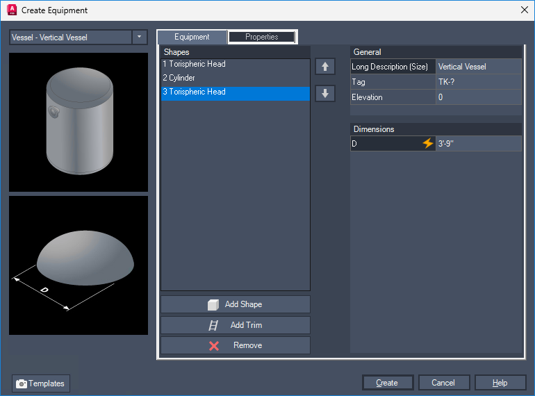
- Click Add to add available shapes for this equipment type. Use the Up and Down arrows to change the position of the shapes.
- Under General, do the following:
- (Optional) To assign a tag to the equipment, click in the Tag box. In the Assign Tag dialog box, in the Type box, enter a type (for example, V for Vessel). In the Number box, enter a unique numeric identifier. Click Assign.
- To assign a description for this piece of equipment, in the Long Description box, enter a description (for example, Vessel-Custom).
- To assign an elevation (the vertical distance from the insertion point to the bottom of the first shape), in the Elevation box, enter a value.
- Under Shapes, click a shape. Under Dimensions, enter dimension values. Repeat this step for each shape dimension you want to change.
Note: When you click a shape to change its dimension, the shape and its dimension values are displayed in the preview image.
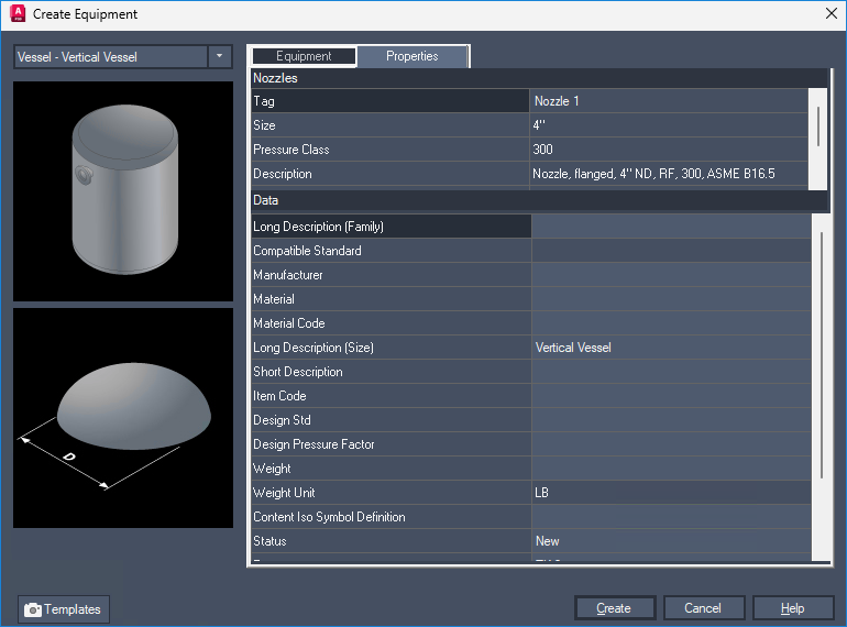
- On the Properties tab, add relevant data for items such as Manufacturer, Material, Size, and so on.
- (Optional) To use this piece of equipment and its data as a template for other equipment pieces, do the following:
- Click Templates.
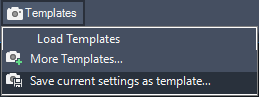
- In the drop-down list, click Save Current Settings as Template.
- In the Save Template As dialog box, navigate to the location where you want to save this template. In the File Name box, enter a template name. Click Save.
Note: The file extension for an equipment template is .peqs. - Click Templates.
- In the Create Equipment dialog box, click Create.
- In the drawing area, click to place the equipment model or enter coordinates at the desired insertion point.
- To orient the equipment model, do one of the following:
- To orient the model to the desired position, enter rotation values or use the compass tool. Press Enter.
- Press Enter to accept the default position. You can use AutoCAD commands such as move, rotate, or 3drotate to further position the equipment.