In AutoCAD Plant 3D toolset, you can create equipment from parametric patterns or user-fabricated models, or add custom equipment to a drawing by converting a 3D DWG model from another program.
When you create an equipment model, you define its geometric information, location, orientation, and non-geometric information (such as an equipment tag or description).
In AutoCAD Plant 3D toolset, you can create and modify 3D models of plant equipment such as tanks, pumps, boilers, and filters.
When modeling equipment, you define its physical dimensions, location, orientation, and other details. You can also create templates from equipment and add nozzles to connect pipes to equipment.
Using equipment patterns, you can create your own piece of equipment simply by changing the dimensions, placement parameters, and placement location in the drawing area.
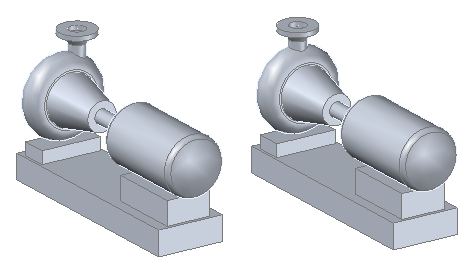
For example, you can create a centrifugal pump from an existing pattern with a modification to one of the values. In the illustration on the left, the position for the nozzle discharge (PF1C) of the centrifugal pump is offset to the right by 4 inches. The illustration on the right shows the nozzle discharge set to 0", or centered on the pump.
You can also create a pattern by stacking individual shapes onto each other and changing the default dimensions and placement parameters of each shape.