A Design report is generated after a Network design run. The report documents how each pipe was evaluated and shows the candidate pipe sizes (see Pipe network catalog) considered, the constraints applied (see Design constraints), any relaxed constraints used, and the final configuration selected by the design algorithm.
The report can be used to:
- review the decisions made during the design process
- identify constraints that control pipe sizing or slope
- diagnose design failures when no feasible candidate exists
- identify pipes where relaxed constraints were used during fallback design
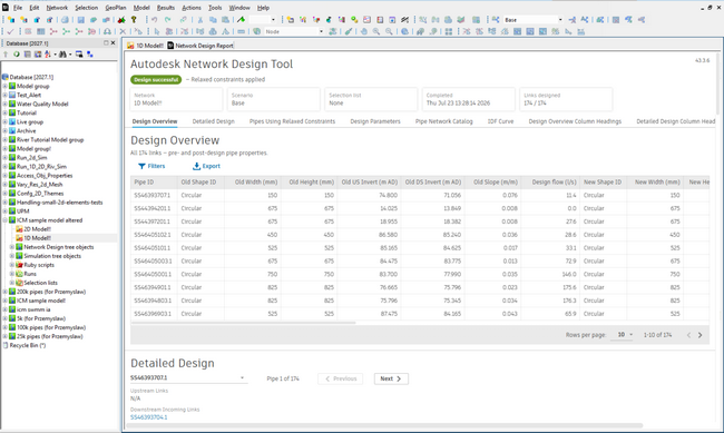
An example of Design Report generated by the Network design tool
Design Overview
The Design Overview table provides a summary of the design results for all pipes processed during the run.
The table includes:
- Original and new pipe size
- Original and new slope
- Design flow
- Governing slope code
- Whether a backdrop was applied
- Notes explaining rejected candidates or design failures
- Relaxed constraints used during fallback design, where applicable
This overview allows users to quickly identify pipes where the design differs significantly from the original configuration or where constraints strongly influenced the result.
Selecting and navigating to pipes
The Design report is linked to the GeoPlan. Selecting one or more pipes in the report selects the corresponding pipes in the GeoPlan, and selecting pipes in the GeoPlan updates the selection in the report.
In the Design Overview table, click a Pipe ID to select the pipe in the GeoPlan and navigate to its entry in the Detailed Design section.
The Detailed Design section also provides links to connected upstream, downstream, and incoming downstream pipes, allowing you to navigate through the network from within the report.
Detailed Design
The Detailed Design section provides pipe-by-pipe information describing how the design decision was reached.
For each pipe, the report includes:
- Time of concentration
- Rainfall intensity used for calculation
- Calculated design flow
- Candidate evaluation table showing all catalog entries tested
- Number of barrels
- Governing slope
- Final selected candidate pipe
- Whether relaxed constraints were applied
- Whether upstream flow adjustment was applied
The candidate evaluation table shows the calculated slope bounds and feasibility status for each candidate pipe size.
The candidate evaluation table allows you to compare each candidate pipe against the applicable hydraulic, geometric, connectivity, and catalog constraints.
Upstream flow adjustment
When the Rational method calculates a design flow that is lower than the flow in the upstream pipe, Network design uses the upstream flow instead. This adjustment is mentioned in the report.
Relaxed constraints in the report
If relaxed constraints are used during a design run, the report identifies the affected pipes and the constraint types that were relaxed. This helps you review local deviations from the main design constraints and understand why the design was able to continue.
Relaxed constraints may apply to slope, velocity, cover depth, or percentage full condition, depending on the relaxed values defined in the Pipe network catalog and the order configured in Design constraints.
The Pipes Using Relaxed Constraints table shows the order in which relaxation operations were applied and the corresponding constraint values. Values changed by a relaxation operation are highlighted, while values that remain within their applicable ranges are not.
Use this information to assess whether the relaxed constraints are acceptable for the design and whether they need to be justified to the approving authority.
Filtering and exporting report data
Use the table filters to limit the rows displayed in the Design Overview and Pipes Using Relaxed Constraints tables. When these tables are exported to CSV, the exported data reflects the current filter. Detailed Design tables are exported in full. The order of the columns shown in the report is preserved in the exported file.
This location works particularly well because filtering/exporting is a report-level interaction, rather than part of the engineering explanation that follows under Candidate evaluation. The Jira specifically distinguishes the export behaviour of the Design Overview/Relaxed Constraints tables from Detailed Design tables.
Candidate evaluation components
Candidate evaluation includes slope components derived from the active constraints.
These include:
- Q-slope (capacity) - slope required to convey the design flow while respecting the maximum percentage full constraint
- V-slope (velocity) - slope required to satisfy velocity limits
- D-slope (depth) - slope required to satisfy cover depth constraints
- S-slope (catalog slope) - slope required by minimum catalog slope limits
- C-slope (connectivity) - slope required to connect to fixed upstream or downstream levels
- F-slope - slope associated with feasibility bounds derived during candidate evaluation
Governing slope
The governing slope represents the constraint that controls the minimum slope required for the selected pipe configuration.
During candidate evaluation, multiple slope requirements are calculated from the active hydraulic and geometric constraints. The governing slope is the largest of these minimum slope requirements and therefore defines the controlling constraint for the pipe design.
The final pipe slope must satisfy this governing requirement while remaining within the feasible slope bounds derived during candidate evaluation.
If the resulting slope is not acceptable, review the governing slope code to identify which constraint is controlling the design.
Governing slope codes
The report uses codes to indicate which constraint controls the design.
- Q - Capacity constraint
- V - Velocity constraint
- D - Depth constraint
- S - Catalog slope constraint
- C - Connectivity constraint
- N - Numerical feasibility bounds
Reviewing the governing slope code helps identify why a pipe was sized or sloped in a particular way.
If the resulting slope is not acceptable, the governing slope code indicates which constraint should be reviewed or adjusted.
Design review recommendation
After a successful design run, it is recommended to review long sections of the designed network to verify that the resulting pipe sizes, slopes, and backdrop placements align with project objectives and local design standards. It is also recommended to run a dynamic simulation (see Simulations)to assess the hydraulic behaviour of the new designed network with the storage structures and the flow controls in consideration.