A network is a dendritic route through the site that is used to perform a Pipe Sizing calculation. This is required as the route that the flows will take and must be dictated in order to perform a sizing calculation using the Rational Method. A dendritic route does not allow for loops or bifurcations, so a single outfall is required for a given sizing to be performed. As such, it is possible to define multiple networks through the site to size different parts of the system.
A dendritic network defines a main route and branches that end at a unique outfall. The following image shows a dendritic drainage network
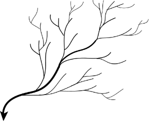
A network is constructed by using a Flow Path as the main drainage route (mainline), and any additional connecting runs (branch lines) are also considered. A Flow Path is used as the basis for building a network as it allows you to make the decisions of where to begin and end the network for sizing, as well as the route to take at a bifurcation (fork).
The network used for sizing is constructed by walking backwards up the Flow Path (mainline) from the most downstream element (outfall) to the first. When branch lines are found, these are then walked up in parallel, with additional branch lines (and subsequent branch lines etc.) from each also considered. At this stage, only connections (as opposed to associations) are considered as these are the items that can be seen as Pipes/Channels and therefore require sizing.
It is possible to view the network calculated by the software from a Path on either:
-
Plan – By highlighting the Flow Path in the Tree View. The Plan View will show the Path in the Mainline colour and then incoming branches in the Branchline colour.
-
Connections – Either by highlighting the Flow Path on the Tree View with the form open, or by selecting the Flow Path by name from the form filter.
Once constructed, the network is then available for use in Network Design.