Connections are links between two elements of the site. They allow a Connection Type to be specified, which will impact the Time of Travel along the Connection and therefore impact the analysis.
By default the connections will sync with their connected Manholes to match Invert Levels.
The flow routing calculations done during the Analysis are described in Analysis of Junctions and Connections.
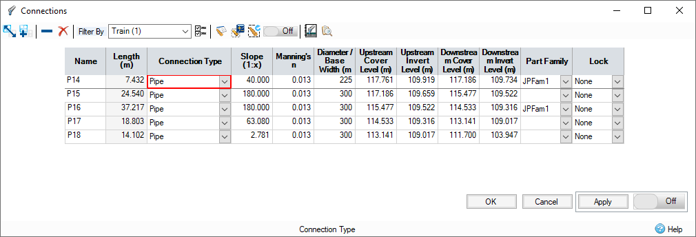
The connections form allows all of the available connections in the phase to be viewed as a table. The spreadsheet then allows the Connection Type and other physical dimensions to be adjusted as required.
The columns displayed are affected by the Connection Types shown and can also be filtered using the Spreadsheet Preferences.
 Change Template – Provides you with the option to change the currently assigned templates for Connections.
 Add To Templates – Provides you with the option to add the currently selected Connection to the Object Templates library.
 Clear The Current Row – Clears data in the current row and deletes the selected Connection.
 Clear All Connections – Clears all data and deletes all Connections.
Filtering the tables
The Filter By drop-down list allows the connections shown to be filtered:
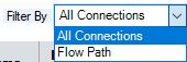
- All Connections – Shows all connections.
- Flow Path – Shows the connections that make up the selected Flow Paths, and its associated network, in the order of flow. This view also allows the Network Design of the pipes and channels in that network.
Spreadsheet Preferences 
Fields can be turned on or off using the Spreadsheet Preferences form, which is accessed from the toolbar at the top of the form. The full set of columns available on both the Input and the Results spreadsheet are shown and can be turned on or off using the tick boxes. These settings will be remembered between sessions.
Network Design Criteria
Allows you to specify the network design criteria to be used to size the pipe/channels along the Flow Path and its network.
Network Design Wizard 
When a Flow Path has been selected on the Filter, it is then possible to perform an Auto Sizing of the pipe/channels that form the network along the flow path. The calculations are completed based on the specified Network Design Criteria when the 'Auto Size' option is clicked. Full details can be found in the Network Design page.
Rerun Network Design Wizard 
When a Flow Path has been selected on the Filter, it is then possible to perform an Auto Sizing of the pipe/channels that form the network along the flow path. The calculations are performed silently using the previous/default settings for the selected flow path.
When this toggle is set to ON and a flow path is selected, any changes to connections form will be automatically applied and the Auto Sizing of the network will be rerun. Auto Sizing will also be rerun if a change elsewhere in the software is made whilst this form is open.
Network Design Report 
A table displaying the results of an auto sizing calculation for a given flow path can be displayed, see Network Design Report for more information.
Audit 
Toggling the audit button will highlight design errors for hydraulic connections.
Slope outside of the min and max slopes provided in the network design criteria are highlighted. This only occurs if the slopes are not locked in the network design criteria, and the slope limit being used is valid.
Backdrops outside of the min and max backdrops provided in the network design criteria are highlighted. This only occurs if the backdrop limit being used is valid, and the backdrop is non-zero. This is highlighted on the upstream end of the outgoing connection and the downstream end of the incoming connection.
Downstream Invert Levels less than the minimum of the connection is highlighted. This only occurs if the minimum is valid.
Levels that break cover will be highlighted. This only occurs if the Min cover depth option is checked in the Network Design Criteria and the minimum cover depth used is valid. The minimum cover depth used is the value in the network design criteria by default, this can be changed on a per connection basis within the connection form.
Bypass Connections
These work like a standard hydraulic connection, but allow the flow not entering an inlet to be routed to an inlet on another Junction/SWC. Note: A bypass connection will not permit reverse flow as it is connected to an inlet.
These will be shown in Italics on the Connections form to highlight the fact they are a bypass connection.
Inputs
Name (Always Shown)
Name of the connection as shown on the plan view.
From
The label of the item at the upstream end of the connection.
To
The label of the item at the downstream end of the connection.
Length (Always Shown)
Length of the connection. If in red – the length was defined by the user. Otherwise, it was calculated using the Connections coordinates from the plan view.
Connection Type (Always Shown)
Type of the connection:
- No Delay – Imposes no effect on the movement of water.
- Lagged Flow – Introduces a time delay on the movement of water based on the Time of Travel value entered. Velocity and Time of Travel columns are shown by default.
- Pipe Connection – Allows a pipe, or series of parallel pipes, to be modelled with a Diameter, Longitudinal Slope and Levels. The dimensions can be entered as required or calculated using the Network Design calculation. Slope, Manning's n, Diameter/Base Width, Upstream Cover Level, Upstream Invert Level, Downstream Cover Level, Downstream Invert Level, Culvert Type and Culvert Entrance columns are shown by default.
- Box Culvert – Allows a Box Culvert, or a series of parallel culverts, to be modelled with a Base Width, Height, Corner Splay, Longitudinal Slope and Levels. The dimensions can be entered as required or calculated using the Network Design calculation. Slope, Manning’s n, Diameter/Base Width, Height, Upstream Cover Level, Upstream Invert Level, Downstream Cover Level, Downstream Invert Level, Culvert Type and Culvert Entrance columns are shown by default.
- Rectangular Channel – Allows a Rectangular channel, or series of parallel channels, to be modelled with a Base Width, Height, Longitudinal Slope and Levels. The dimensions can be entered as required or calculated using the Network Design calculation. Slope, Manning's n, Diameter/Base Width, Height, Upstream Cover Level, Upstream Invert Level, Downstream Cover Level and Downstream Invert Level columns are shown by default.
- Trapezoidal Channel – Allows a Trapezoidal channel, or series of parallel channels, to be modelled with a Base Width, Side Slope, Height, Longitudinal Slope and Levels. The dimensions can be entered as required or calculated using the Network Design calculation. Slope, Manning's n, Diameter/Base Width, Height, Side Slope, Upstream Cover Level, Upstream Invert Level, Downstream Cover Level and Downstream Invert Level columns are shown by default.
- Triangular Channel – Allows a non-symmetrical Triangular channel, or series of parallel channels, to be modelled with a Side Slope, Height, Longitudinal Slope and Levels. The dimensions can be entered as required or calculated using the Network Design calculation. Slope, Manning's n, Height, Side Slope, Upstream Cover Level, Upstream Invert Level, Downstream Cover Level and Downstream Invert Level columns are shown by default.
- Custom Connection – Allows a custom connection, or series of parallel connections, to be modelled with a Custom Cross-Section, Longitudinal Slope and Levels. The dimensions can be entered as required or calculated using the Network Design calculation. Slope, Manning's n, Upstream Cover Level, Upstream Invert Level, Downstream Cover Level, Downstream Invert Level and the Cross-Section columns are shown by default.
-
Arch – Allows an Arch Culvert, or series of parallel culverts, to be modelled similarly to a Box Culvert (with a Base Width, Height, Corner Splay, Longitudinal Slope and Levels). The dimensions can be entered as required or calculated using the Network Design calculation. Slope, Manning’s n, Diameter/Base Width, Height, Upstream Cover Level, Upstream Invert Level, Downstream Cover Level, Downstream Invert Level, Culvert Shape, Culvert Type and Culvert Entrance columns are shown by default. Note that for Arch culverts with a ‘Pipe Arch’ or ‘Structural Pipe Arch’ Culvert Shape, Diameter/Base Width is fixed at 1.37 x Height.
- Ellipse – Allows an Ellipse Culvert, or series of parallel culverts, to be modelled similarly to a Box Culvert (with a Base Width, Height, Corner Splay, Longitudinal Slope and Levels). The dimensions can be entered as required or calculated using the Network Design calculation. Slope, Manning’s n, Diameter/Base Width, Height, Upstream Cover Level, Upstream Invert Level, Downstream Cover Level, Downstream Invert Level, Culvert Shape, Culvert Type and Culvert Entrance columns are shown by default.
Slope
Longitudinal slope of the connection. This is calculated based on the fall, between the upstream & downstream invert levels, along the length of the connection. Entering a value for the slope will therefore adjust the downstream invert level.
Manning's n
Manning's coefficient for the connection, which will be used in velocity and flow/capacity calculations.
Colebrook-White Roughness
Colebrook-White roughness for the connection, which will be used in velocity and flow/capacity calculations.
No. of Barrels
Number of barrels/channels laid parallel.
Diameter/Base Width
Diameter of the connection of a Pipe, or base width of a Rectangular or Trapezoidal channel.
Height
Height of a Rectangular, Trapezoidal or Triangular channel.
Cross-Section
Clicking this button allows the cross-section of a custom connection to be defined.
Corner Splay
Introduced into a Box Culvert for pipe-strengthening purposes. This value cannot be greater than half the current Width or half the current Height. The default value is 0 and will not be automatically adjusted.
Side Slope
Slope of the sides of a Trapezoidal or Triangular channel.
Curved
Flag to indicate if the connection is curved. This can be used to toggle a connection between straight and curved.
Curve Easting
The easting of the curve coordinate.
Curve Northing
The northing of the curve coordinate.
Upstream Cover Level
The cover/exceedance level at the upstream end of the connection. Levels may be set automatically if sufficient data exists, see individual connection type pages for more details.
If the upstream node is a junction, then the upstream cover will be set synced to the junction, changing the cover here will also change the junction and any other upstream connections to the same junction.
Upstream Invert Level
The invert level at the upstream end of the connection. Levels may be set automatically if sufficient data exists, see individual connection type pages for more details.
Downstream Cover Level
The cover/exceedance level at the downstream end of the connection. Levels may be set automatically if sufficient data exists, see individual connection type pages for more details.
If the downstream node is a junction, then the downstream cover will be set synced to the junction, changing the cover here will also change the junction and any other downstream connections to the same junction.
Downstream Invert Level
The invert level at the downstream end of the connection. Levels may be set automatically if sufficient data exists. See individual connection type pages for more details.
Part Family
The part family associated with this connection. This is available for closed connections only.
The values of the connection Wall Thickness, Material, Trench Width, Bedding Material and Surrounding Material properties are set according to the closest matching part size from the selected part family.
For pipe connections, the part size is matched by diameter. For other connection types, the part size is matched first by height and then by width.
For more information, see Part Families.
Lock
The Lock state: If "None" is selected, no locking occurs. If "Levels" is selected, the Invert Levels of the given connexion are locked and thus will not be synchronised. If "All" is selected, exclude the given connection from Network Design calculations and invert level synchronising.
Entry Loss
The loss coefficient associated with energy losses at the entrance of the connection. Refer to Analysis of Junctions and Connections for more details on this topic.
Exit Loss
The loss coefficient associated with energy losses at the exit of the connection. Refer to Analysis of Junctions and Connections for more details on this topic.
Average Loss
The loss coefficient associated with energy losses along the length of the connection. For example where a pipe is curved or has intermediate points to pass around corners. Example values can be seen in the Hydraulic Design of Highway Culverts, section 5.4.
Minimum Downstream Invert Level
The minimum invert level at the downstream end of the connection. This is not required but may be set in order to inform network design/positioning.
Minimum Cover Depth
The minimum cover depth of the connection. This is not required but may be set and will overwrite a global value if set. See Network Design summary wizard page for more details.
Flow Restriction
The base flow used in network design calculations if Use Flow Restrictions is checked in the Network Design criteria. This value is automatically calculated as the discharge rate of the upstream outlet with a water level equal to the free-board level for Stormwater Controls or the cover level for Manholes.
Velocity
Velocity of the flow in the connection –Lagged Flow only.
Time of Travel
Time of travel of the flow through the connection – Lagged Flow only.
Culvert Shape
The shape of the culvert connection – culvert shape options will be presented for Arch and Ellipse only. For all other connection types, the Culvert Shape property is greyed out.
Culvert Type
The culvert type as per FHWA HDS-5 – Pipe, Box Culvert, Arch and Ellipse only. For all other connection types, the Culvert Type property is greyed out.
Culvert Entrance
The culvert entrance as per FHWA HDS-5 – Pipe, Box Culvert, Arch and Ellipse only. For all other connection types, the Culvert Entrance property is greyed out.
Wall Thickness
The wall thickness of the part size matched to the connection from the selected part family. For more information, see Part Families.
Material
The material of the part size matched to the connection from the selected part family. For more information, see Part Families.
Trench Width
The trench width of the part size matched to the connection from the selected part family. For more information, see Part Families.
Bedding Material
The bedding material of the part size matched to the connection from the selected part family. For more information, see Part Families.
Surrounding Material
The surrounding material of the part size matched to the connection from the selected part family. For more information, see Part Families.
Apply Toggle
When this toggle is set to ON, any changes made to the connections form will be automatically applied. Any changes not applied before setting the toggle to ON will be applied. If the Rerun Network Design Wizard toggle is set to ON, this toggle will also be set to ON.