3D Elements View
Description
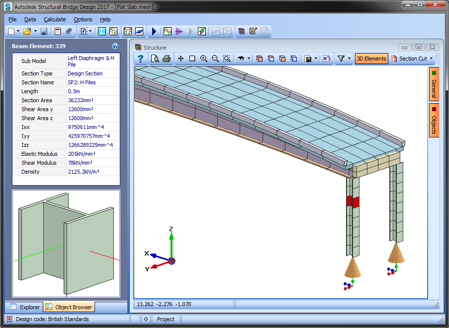
A refined analysis model can be viewed with 3D object rendering. This allows the user to check the structural integrity of the model. The 3D objects rendered include beam elements, finite elements, supports, beam releases and post tensioned tendons. Features include:
- 3D, 2D or wire frame view modes
- An Object Browser for inspecting details of a selected object (local axes and section properties, fixity, etc.). The selected object could be a beam or finite element, support or release.
- Rendering of features such as cracked beam sections, staged construction, and voided sections.
- Member colour schemes. Model can be coloured by sub model, property, elasticity or member. A colour key can be shown for the submodels or property groups.
- Member Selection Filtering.
- Cross section viewing.
- Print, save and load view commands.
Outline Procedure
This form is accessed via File | 3D Elements View from the main menu, or by the shortcut Ctrl-M.
Form Graphic
Field Help
Common toolbar commands are detailed in the topic Analysis Graphics Toolbars field help. Commands exclusive to the 3D Elements View are as follows:
3D Elements
Toggle this button to switch between 3D and 2D view configurations. Annotation is only available for the 2D Elements view. The member annotation is aligned to the local x axis.
Section Cut
Toggle this button to switch between a section cut view and the full model view. When switching to section cut mode for the first time, a prompt will be shown to pick the cut line. This is done by two mouse clicks across the model. For example, in plan view, a click either side of the model will give an elevation cut view.
The drop down arrow on the Section Cut button shows a menu with the following additional commands:
| Command | Description |
|---|---|
| Pick Cut Plane... | Select to define section cut plane. |
| Off | Switches off section cut mode. |
| Cross Section | Sets section cut mode to cross section. |
| Forward Division | Switch to mode which hides model behind section cut. |
| Backward Division | Switch to mode which hides model in front of section cut. |
| Capping Mode | The cut face can be hatched, solid or clear. |
Dynamic View Menu | More...
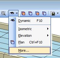
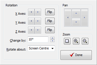
Use this form for finer control of the dynamic view.
Refer to the General toolbar field help for additional view configuration items (i.e. colour scheme, wire frame view, etc.).