Once you click the New Design Line icon  on the toolbar, the Design Line Takeoff dialog, shown below, is displayed. The next step is to select either the size-based method of entering the Design Line, or the constraints-based method.
The sized-based entry method is enabled by clicking the Entry tab from within the selected service. Sized-based entry for Design Line can also be enabled/disabled for a specific service from Setup Services dialog  Services Design Entry tab Enter By Size option. Disabling this option results in constraints-based entry being the default for the selected service. This can additionally be accessed from the Design Line Service Pallet Menu Bar.
The Enter by Size method enables entering the exact size of a duct or pipe.
For more information on the other Design Line controls, see Design Line Toolbar and Menus and Design Line Service Pallet Toolbar.
Entry Tab
To enter the information necessary for sized-based entry of a Design Line, use the options available on the Entry tab. (The Criteria tab is used for constraint-based Design Lines.)
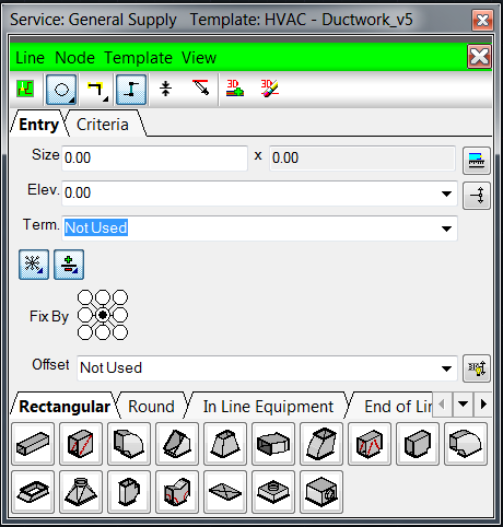
The following options, which are intended for sized-based Design Line entry, are available on the Entry tab.
Size: Entry field for application to the Design Line. One dimension entered will automatically draw Round. Two dimensions entered will be treated as either Rectangular (default) or Oval via the Shape selection field of the toolbar. The first field is width. The second field is for height.
 Pick Length: When specifying a reduction to the line or shape change, after dimensions are entered for the reduction, you are able to select the Pick Length button and use the underlay or reference point on the drawing to dictate the length required.
Elevation (Elev.): The height at which the Design Line will be drawn in the model. Use Fix By to determine line position in relation to the object being drawn. When drawing elevations manually (i.e. not using the Add Riser button  ), ensure the Elevation field is set to "Not Set", else the line will draw to the specified elevation each time. For entering imperial units, you can enter feet (') and inches ("). For example, to enter twelve feet and 6 inches, type 12' 6".
Add Riser / Elevation change: Use the Add riser option to specify a vertical movement. Entering a new elevation and then selecting this option will draw a line to the new elevation. Holding the Add Riser button down, allows selection of an alternative angle for how to reach the elevation specified. Defaults are 90 degrees.
Terminal (Term.): The height at which terminals are to default to when placed onto the Design Line. See Design Line Terminal Styles for preferences of the behavior. For entering imperial units, you can enter feet (') and inches ("). For example, to enter twelve feet and 6 inches, type 12' 6".
 Fix By: When you click the Fix By button, the Fix By graphic becomes active, and you can specify Fix By positions.
 Fix By: When the Fix By option is enabled, this Fix By graphic lets you specify where the Design Line is to be positioned in relation to the fill. Clicking the various circles (or radio buttons) on this Fix By graphic let you indicate alignment positions, such as Flat Right, Flat Top or Central, to takeoff the Design Line.
 Offset: When you click the Offset button, the Offset field displays and you can specify an offset when placing the Design Line.
 Auto Update Line Position: When Auto Update Line Position is enabled, using the Fix By setting will automatically draw a small line to the Fix By position automatically. You can just specify the new Fix By position and let the software dictate the line position location. The example below shows a center line movement to Flat Bottom.
Using the Automatic Method
The following example shows a center line movement to Flat Bottom.
- Start in 600x600 duct and move to the position where the offset is required.
- Selecting the new Fix By position when the is enabled shifts the Design Line to the new position.
- Type in the reducing size, and then continue to draw in the new Fix By position (Flat Bottom Right).

Using the Manual Method
The example below shows a 1000x1000 rectangular duct tapering to 600x600 keeping the right side of the duct "Flat Right". At the time of changing the Fix By position, you can point the Design Line in the required direction, and then type half the width (500) in Line Create mode. Press Enter to confirm the length required, then at the required Flat Right position, select the Fix By from Central to Right, as shown in the diagram below. Together with the reduction in size, using the dimension fields will allow you to draw the line Flat Right. Once Filled in 3D, the alignment should show that the duct is straight on the right side.
