The Pattern Takeoff dialog is used to set the pattern template values and then accept the pattern into the job. This is accomplished using the options available on the Dimensions, Options, Items and Connectors tabs. The values set on these tabs are used to generate the pattern developments, and therefore the subsequent NC code.
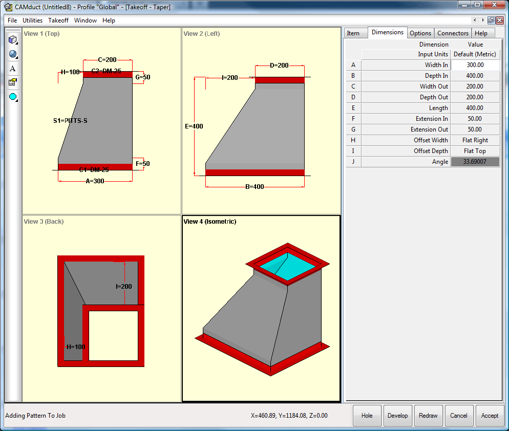
The Pattern Takeoff dialog is organized into two sections. The Pattern View section on the left is divided into four subsequent views, showing the pattern from different perspectives. On the right, the Data Input section is where the pattern's dimensional data is entered. There are buttons at the bottom of the dialog that are used to Add Hole (if supported by the pattern), Develop, Redraw, Cancel and Accept the pattern respectively.
The Pattern View Section
The four views of the pattern by default display the Plan view (top left), the Right hand view (top right), the Front view (bottom left) and the 3-D Isometric view (bottom right), based on the default First Angle Projection. All the views can be moved to display different views of the fitting.
-
Click and hold the left mouse button anywhere in the bottom right view window and move the mouse in the desired direction.
If Third Angle Projection is preferred, you can switch the views.
-
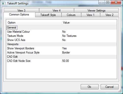
Right-click on the top right window, View 2 , and select Settings, or click the Settings button
 located in the Takeoff toolbar. The Takeoff Settings dialog displays. This dialog has 8 tabs that let you control a variety of settings within the Takeoff dialog. For more information, see
Takeoff Settings Dialog.
located in the Takeoff toolbar. The Takeoff Settings dialog displays. This dialog has 8 tabs that let you control a variety of settings within the Takeoff dialog. For more information, see
Takeoff Settings Dialog.
The Data Input Section
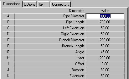
The Data Input section of the Takeoff dialog (the right side of the dialog) allows the user to enter a variety of dimensions and other important information about the item. For most patterns, a large variety of sizes, shapes, and options are possible from a single pattern. This example below uses a single pattern, a Pipe with Branch (CID 851), to describe the many options available on a single pattern using the Takeoff dialog.
By changing the data in the input section, it is possible to redraw the fitting, and see the changes as they affect the pattern. The lettering convention used throughout only applies if the pattern has no locked dimensions.
Dimensions Tab
The Dimensions tab lets you specify a variety of dimensions that control the sizes of the various parts of the item.
-
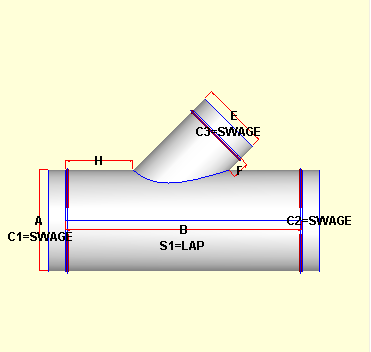
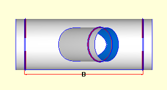
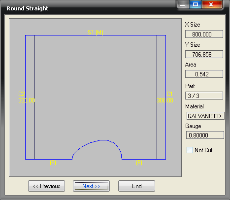
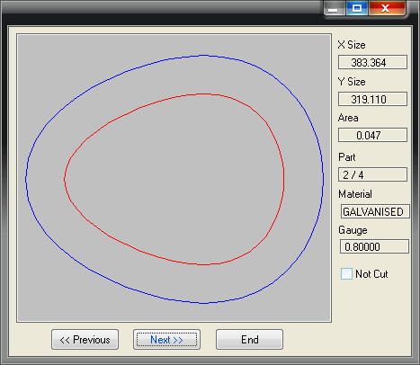
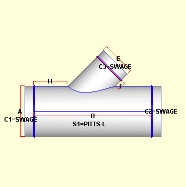
On the Dimensions tab, enter the dimensions for the item as required. The example below shows the list of dimensions available for this sample Pipe with Branch (CID 851) item. For other items, the available dimensions would be different. On the left hand side of this dialog, there is a list of letters, in this case A - K. When used in conjunction with the Pattern View section, it is possible to relate each dimension to the fitting itself. The images below illustrate the location of the Pipe Diameter dimension (A), as well as some of the other dimensions (B = Pipe Length, E = Branch Diameter, F = Branch Length, H = Inset).
-
It is also possible to see which Seams and Connectors have been applied to the fitting. In the images above this is denoted with the C1 and C2 entries for the Connectors and the S1 entry for the Seam.
Options Tab
The Options tab lets you configure the options that are available for the fitting. The list of options that display on this tab are different for each type of fitting.
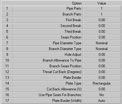
The list below describes the options for this particular fitting, shown in the example above, and what happens when they are applied.
-
Pipe Parts allows the user to specify how many parts the pipe will consist of. The possible values range from No Pipe to 4 Parts. If No Pipe is selected, the development view will not include the pipe development and when the pattern is nested there will be no pipe in the nest. This could be useful in a situation where the pipe already exists and the pattern is being used to set a branch with the correct diameter to sit on to the pipe.
-
The Branch Parts option also ranges from No Branch to 4 Parts. Again this is useful in a situation where the branch is already cut, and the pattern is being used to cut a pipe with a correctly dimensioned hole in it.
-
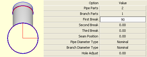
The next three break options govern where the splits in the pipe will occur if it is made of more than one part. These breaks are given in degrees going clockwise from the 3 o'clock position on View 2. They are only used when the pipe is made out of the corresponding number of parts.
-
The diagram shows a 90 degree break in the pipe. The red lines denote the seam positions. As can be seen, the first seam is at 0 (or 360 degrees - the two values are equivalent) and this is set by the Seam Position value. The first break is used because the Pipe Parts option is set to 2.
-
The Seam Position option works in exactly the same way as the Breaks. The value is taken from 3 o'clock looking at view 2 and moves clockwise with a positive input value. This seam position applies to the pipe and should not be confused with the Branch Seam Position.
-
The Pipe and Branch Diameter Types can be set to either Nominal, Inside or Outside. These options determine how the Pipe and Branch Diameter values are implemented. They use the gauge set on the Item page to determine the metal thickness and then adjust the diameter of the duct accordingly. For example, the nominal pipe diameter of 100mm cut on a 1mm thick sheet will give an inside diameter of 99mm and an outside diameter of 101mm. The diameter value is therefore considered to refer to one of these three settings depending on the option set here. This is particularly useful if working from a list of dimensions that are OD or ID and thus eliminates the need for manual calculation which can lead to errors.
-
The Hole Adjust option allows for the hole in the pipe that accommodates the branch to be increased or decreased in size. A positive value will give a bigger hole and vice versa. This works on the principle that the input is the amount by which the diameter should increase or decrease by, not the radius.
-
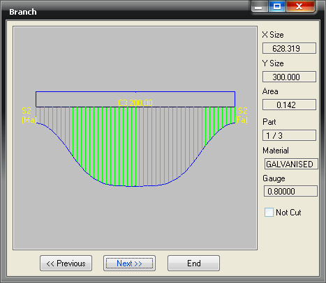
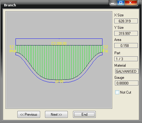
Branch Allowance to Pipe gives a turnover allowance for attaching the branch to the pipe. A value here applies a uniform turnover right across the bottom of the branch. The image below left shows the branch without any Branch Allowance to Pipe set. The image below right has 20mm allowed, note how the development has changed and that the size has altered to reflect the allowance added.
-
The Branch Seam Position allows the user to set position of the seam. This value is taken from the rightmost extents of the branch in view 1 and in a situation where the branch angle to the pipe is less than 90 degrees it can be said to run down the throat at a zero value. The seam moves around the branch in a clockwise direction given a positive value. The position is given in degrees.
-
The Throat Cut Back and Cut Back Allowance (%) work in conjunction with one another to enable the operator to remove some or all of the Branch Allowance to Pipe through a specific amount of cut back. The Throat Cut Back value will remove an arc around the throat for ease of manufacture. The throat can often hinder the metal worker from being able to form the pattern correctly and the Throat Cut Back enables an exact amount of the Branch Allowance to Pipe to be cropped from the throat. The value works by cutting back the allowance from a zero position at the apex of the throat and working radially around the pipe by a number of degrees. If a value of 90 were given the result would be 90 degrees of cut back on either side of the center-point of the throat, effectively removing half the allowance. The Cut Back Allowance sets the depth of the Branch Allowance to Pipe that should be left on the development. A value of zero removes the entire allowance. Any other value will leave that percentage of the full allowance in the throat region. The combination of values outlined above allows flexibility in constructing the part.
-
The Plate Border option allows the user to produce a plate, instead of, or as well as, the Pipe for the fitting. This gives can be useful when the branch is fitted to existing pipe. The amount entered here will be the amount of material placed all around the developed hole.
-
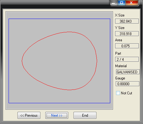
The Plate Type option can either be Rectangular or Hole. If Rectangular is selected the image below left will be relevant. If Hole is selected a plate similarly shaped to the developed hole itself will be used as displayed below right.
-
The Plate Border Width option allows the user to enter a different amount to be used on the plates width. If this is left at Auto the amount entered in the Plate Border field will be determine how much material will be placed all around the hole. If an amount is entered here, the border dimensions of the plate will be obtained from the Plate Border and the Plate Border Width fields.
-
If Yes is elected in the Use Pipe Seam for Branches option, the branch will automatically use the same seam as the pipe. If this is set to No, then the seam selected in the S2 field of the Connectors tab will be used.
With a combination of all of the Dimension and Option settings listed, many possibilities exist from just one pattern template. The purpose is to provide flexibility in how the ductwork is manufactured and to enable ease of assembly by cutting the parts in a logical and familiar way for sheet metal workers.
Item Tab
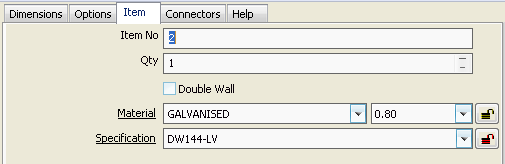
The Item tab specifies other important information. By default the Item tab is displayed as shown below.
-
The Item No field allows the user some identification for an inputted part. This can be either letters or numbers.
-
The Qty fields sets the amount fittings to be manufactured.
-
The Material and Gauge fields allow a specific material and gauge for the fitting. This is usually determined automatically by the Specification selected.
-
The Notes fields allows the user to enter notes to be attached to the fitting. These can either be typed in manually or selected from a pre-defined list in the drop-down menu.
-
Selecting a Specification allows several factors to chosen automatically, these include the Material, Gauge, Seams, Connectors and others.
It is also possible to enable more options on the Item tab. For more information see the Takeoff Options.
Connectors tab
The Connectors page allows connectors and seams to be assigned to the pattern after they have been set up in the Pattern Database. This method allows a common series of allowances to be applied to all connector ends of a pattern and for a seam to be identified by name rather than by the size of allowance. This is helpful in that printouts of the pattern will list the actual connectors and seams rather than a series of turnovers and allowances. If Specifications have been set up, it is possible that the seams and connectors will be selected automatically. Even if this is the case, it is still possible to change the seams and connectors to be applied.
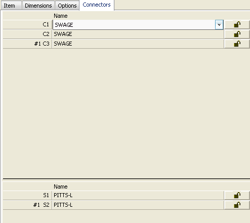
The Connectors section at the top of the tab shows a list of the connectors available in the fittings. Once again, it is possible to relate which connector will be added and where.
-
Click on the drop-down menu to select a different connector as required
The Seams section, similarly to the connectors, shows a list of seams in the fitting. As before, it is possible to relate which seam will be applied and where.
When the all Dimensions, options etc have been entered, it is possible to accept the part.
-
Click Accept or press the End key to accept the part.