Service buttons are used to control actions for when items are placed onto the active Design Line. The user is able to specify which actions are to be performed for individual circumstances. The types of actions performed vary from 2D Symbol placement to the application of conditions (For example: To control when certain items are to be used Screwed fittings up to 50mm, Welded above 50mm for mechanical or up to 250mm pressed, above 250mm fabricated for Round ductwork). Certain types of buttons require configuration of a Fitting type in order for them to be Design Line compatible. Behind each button is a Fitting type setting which will be discussed in more detail in this help topic.
Accessing Button Properties
- Right click on a button
 Select Button Properties from the Right Click menu that appears.
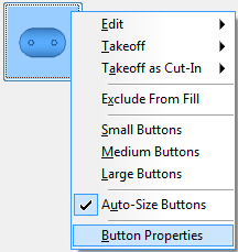
- The Button Properties dialog allows options to be set for Design Line compatibility.
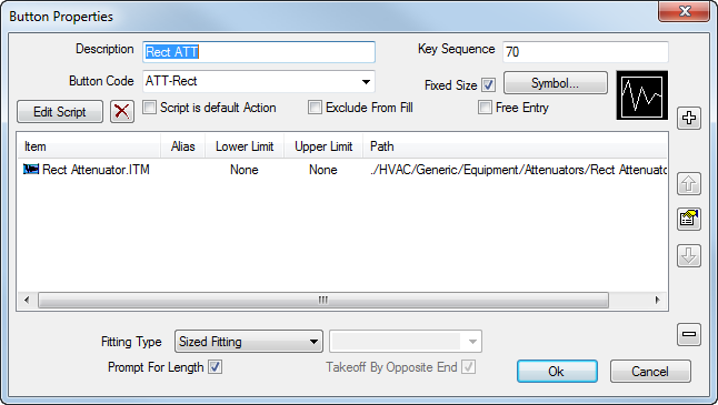
The most common and important options from this dialog are as follows:
- Button Code: Requirement for detection of Design Line fill. Setting a unique code on a button will isolate items to fill the particular item in question. Sharing codes amongst similar buttons will perform the fill routine of the first button code in the service that shares the same name as the one placed into the Design Line. Buttons with no code cannot be filled in 3D (Coupling patterns are exceptions to this rule as these can be automated for entry using connectivity rules).
- Key Sequence: Used within Quick Takeoff and is for fast entry of buttons in particular relating to our Estimating software. Users can type the Key Sequence followed by the Enter key to bring up a particular item into view ready for takeoff. Key sequences are also used to map to the Digitizer template when using Digitizer takeoff.
- Symbol: Used for referencing/displaying a 2D image onto the Design Line which is visible to the user and applied to the Design Line layer (2D DXFs).
- Exclude from Fill: Skips the button from filling in 3D routines and attempts to fill the next item if sharing the same Button Code (Mapping).
- Fitting Type: Used to perform actions when placing buttons onto the active Design Line. More information below from the Fitting Types heading.
- Prompt for Length: Prompts the user with an entry field at the time of placement. This adapts the items length field (if unlocked and available) with the value entered for inclusion onto the line. The filled in item will have the length specified. Useful for Attenuators.
Fitting Types
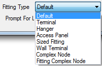
Default: No action performed at takeoff. Will just attempt to apply the item behind the button to the Design Line when filled in 3D.
Terminal: Used to position the item at the ceiling height when placed onto the Design Line. If drawing the Design Line at an elevation, when placing terminals such as Grille Boxes onto the Line, a ceiling height must be entered to ensure the riser is also drawn automatically to that height.
Hanger: Used on the Hanger pattern CID 838. When this item is assigned to a button, and with the Fitting type set to Hanger, this will identify to the software that the button is ready to be called for from the Service Template Support Specification.
Access Panel : Used to apply to buttons containing CID 504 and CID 580 (Access Panel items). When the button is placed on to the Design Line, this prompts for a position (Top, Bottom, Left, Right). When Filled, the Access Door will be positioned in the rotation specified.
Sized Fitting : When applied to items such as Attenuators or Silencers, the size in the Design Line Takeoff, will be the size the Line fills this item with. For example, if placing a 1000x1000 Attenuator onto a 800x800 Design Line, when filled in 3D, the software will assign two Tapers either side automatically.
Wall Terminal : Normally applied to Louvre's that are not using Ceiling heights and want to remain at the Elevation being drawn. Application of Wall Terminal allows for Size entry to be made prior to placement and when calculated for Fill, will perform the necessary transition piece automatically.
Complex Node : Used for complicated scenarios where lines are Offset at junctions. Certain patterns can be used to adapt themselves to meet the points of the Design Line. Please read our Design Line Complex Nodes for further information on the patterns supported and steps to follow.
Fitting Complex Node : Allows the user to takeoff an item using insertion points and attacher methods. When set on a button and is positioned onto the End of a Design Line, the user is prompted with dimensional data / insertion options that are then to be confirmed from the Fitting Complex Node toolbar. For more information please view the Design Line Fitting Complex Nodes .