Generate a Probe Geometry operation
This feature is part of an extension. Extensions are a flexible way to access additional capabilities in Fusion. Learn more.
On the Manufacture workspace toolbar, click Inspection > Probing > Probe Geometry
 .
.The Probe Geometry dialog opens.
On the Tool tab, click Select to pick a probe. If you have not created a probe to use, in the left panel of the dialog, from the Fusion Library, pick a probe from the Probes folder.

On the Geometry tab, in the Probe Mode list, select Model or Stock, depending on what you want to probe.
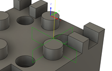
Tip: Place the pointer over a parameter for more information.Ensure Probe Surfaces, or Probe Stock Surfaces, is active, then, on the canvas, click a face, or faces, on the model or stock. For example:
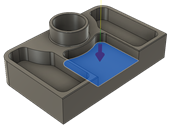


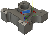
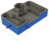
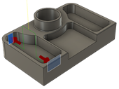
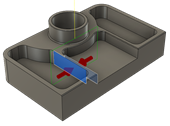
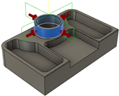
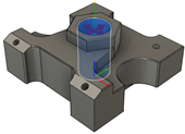
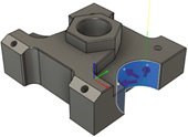
Select a Probe Type to determine the inspection method for the selected surface. Choose:
A probing cycle option for measuring and verifying features using macros on the CNC machine, or
A geometric fitting option for inspecting cylindrical or planar surfaces from probe paths without using macros.
Note: Further options are available in the dialog and differ depending on what Probe Type you choose.
Enter Tolerances for the feature. The various tolerances you can set depend on the selected surface and chosen Probe Type.
Optional steps:
To stop the CNC machine, and display a message on the controller, when a feature is out of tolerance, in the Actions tab, select the Out of Position, Wrong Size, or Askew checkboxes.
If you are using a probing cycle and want to improve the accuracy of future machining operations, select the Update Tool Wear checkbox, then click Select and choose the last operation that machined the feature.
If you are using a probing cycle and want to enable the results to be displayed on the machine-tool controller, and generate a results file, select the Print Results checkbox.
Click OK.
The operation is generated.
Now post process the Probe Geometry operation to create NC code, which you can then transfer to the machine controller. If there is a live connection between Fusion and the CNC machine, import the inspection results in real-time as the NC code runs on the CNC machine. Alternatively, if a live connection is not available, import the inspection results from a machine-generated results file.