Inspect Surface reference
This feature is part of an extension. Extensions are a flexible way to access additional capabilities in Fusion. Learn more.
Use the Inspect dialog to specify the details of an Inspect Surface operation.
Manufacture > Inspection > Probing > Inspect Surface ![]()
The dialog contains the following settings:
Tool
Click Select to open the Select Tool dialog, where you can find and select a probe.
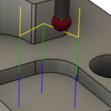
Link Feedrate
Defines the speed of the probe during link moves, which are performed before and after the probe leads in and then touches the part. Link moves are displayed in yellow on the canvas.
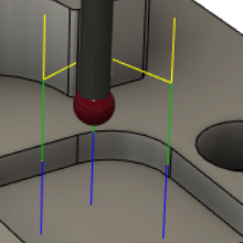
Lead-In Feedrate
Defines the speed of the probe during lead moves, which are performed before and after the probe touches the part. Lead moves are displayed in green on the canvas.
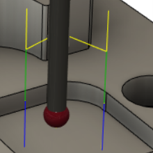
Measure Feedrate
Defines the speed of the probe during measure moves, which is when the probe touches the part. Measure moves are displayed in blue on the canvas.
Tool Orientation
Select an option to determine how the probe is oriented.
Positions
Click positions on the CAD model on the canvas to specify the contact points that are to be probed. Arrows are displayed on the model and their positions reflect the surface normal.
To reposition a contact point, click and drag the corresponding point on the model.
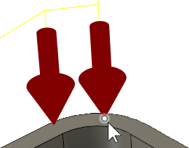
To delete a contact point, hold the Shift key and click the corresponding point on the model.
Order
Lets you choose the order that the specified contact points are probed.
You can have the points probed in the order that you created them. Or choose an optimized order that minimizes the distance that the probe travels along the X and Y axes. If you choose an optimized order and you create, reposition, or delete a point, the order is automatically updated.
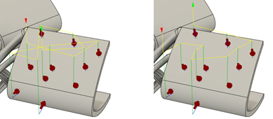
Example of Order by Selection (left) and Optimize XY Travel (right).
Reverse Order
Swaps around the order that the specified contact points are probed, so that the point that is probed first is instead probed last.
Surface Offset
Enter a positive or negative value to compensate for surface thickness. This offset is applied normal to the surface at the contact points, with positive values in the direction of the probe.
A value of 0 measures contact points at the surface.
Upper Tolerance and Lower Tolerance
Enter a positive or negative value to specify the acceptable range of deviation of the measured contact points from the Surface Offset.
When the inspection results are imported, any measured contact points outside the tolerance range are considered out of tolerance and any points within the range are considered in tolerance.
Approach
Enter a value to specify the distance from the surface normal where the probe starts to approach the surface at the Measure Feedrate. By default, Approach is twice the probe diameter.
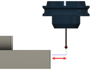
Overtravel
Enter a value to specify the maximum distance the probe can move beyond the expected contact point and still record a measurement.
If no contact is made within this distance, the probe returns an invalid measurement.
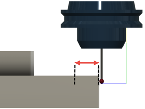
Heights
The different heights for the probe.
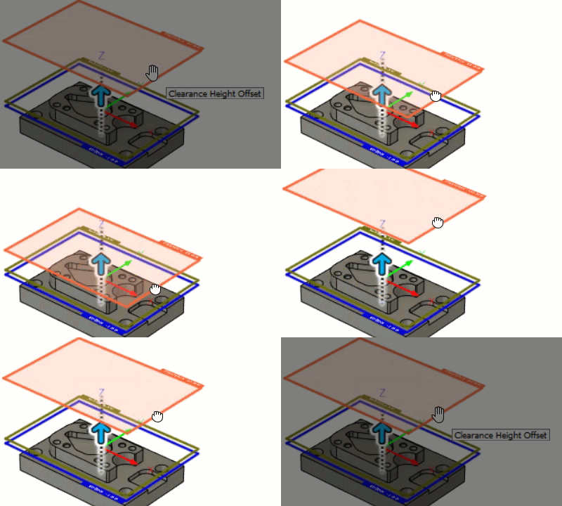
Clearance Height
The first height that the tool moves to on its way to the start of probing and the point that it returns to after the process is finished. This position can be defined in reference to the stock, the model, another reference, or a user-selected position. The height is shown in orange.
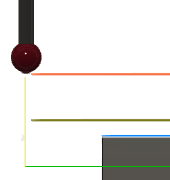
From defines the reference for the Clearance Height:
- Retract height: Incremental offset from the Retract Height.
- Model top: Incremental offset from the Model Top.
- Model bottom: Incremental offset from the Model Bottom.
- Selection: Incremental offset from a Point (vertex), Edge, or Face selected on the model.
- Origin (absolute): Absolute offset from the Origin that is defined in either the Setup or in Tool Orientation within the specific operation.
Offset is a shift relative to the From selection. Enter a value, or drag the orange height on the canvas.
Retract Height
Sets the height used between probing individual contact points. The height is shown in dark green.
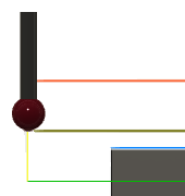
From defines the reference for the Retract Height:
- Clearance height: Incremental offset from the Clearance Height.
- Model top: Incremental offset from the Model Top.
- Model bottom: Incremental offset from the Model Bottom.
- Selection: Incremental offset from a Point (vertex), Edge, or Face selected on the model.
- Origin (absolute): Absolute offset from the Origin that is defined in either the Setup or in Tool Orientation within the specific operation.
Offset is a shift relative to the From selection. Enter a value, or drag the dark green height on the canvas.
Out of Position
When enabled, instructs the CNC machine to stop probing and display a message on the controller when a measured contact point is out of tolerance. Evaluation of surface inspection results at the controller provides real-time verification.
When deselected, no action is taken.
Clearance and retract heights and approach and overtravel distances
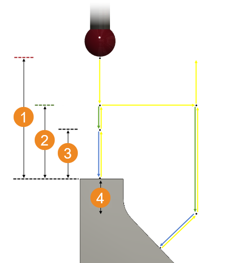
 Clearance Height
 Retract Height
 Approach
 Overtravel