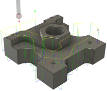
Generate an Inspect Surface operation
This feature is part of an extension. Extensions are a flexible way to access additional capabilities in Fusion. Learn more.
On the Manufacture workspace toolbar, click Inspection > Probing > Inspect Surface
 .
.The Inspect dialog opens.
Tip: Place the pointer over a parameter for more information.On the Tool tab, click Select to pick a probe. If you have not created a probe to use, in the left panel of the dialog, from the Fusion Library, pick a probe from the Probes folder.

Specify the speeds at which the probe moves:
Enter a Link Feedrate to define the speed of the probe during link moves, which are performed before and after the probe leads in and then touches the part. Link moves are displayed in yellow on the canvas.
Enter a Lead-In Feedrate to define the speed of the probe during lead moves, which are performed before and after the probe touches the part. Lead moves are displayed in green on the canvas.
Enter a Measure Feedrate to define the speed of the probe during measure moves, which is when the probe touches the part. Measure moves are displayed in blue.
Note: The Measure Feedrate must match the calibration feedrate on the CNC machine to ensure best accuracy.
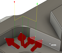
On the Geometry tab, ensure that Positions is active, then, on the canvas, click the model to specify points to be inspected by the probe.

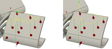
Choose an Order for the specified points.

Example of Order by Selection (left) and Optimize XY Travel (right).
Tip: To swap around the order that the points are probed, so that the point that is probed first is instead probed last, select the Reverse Order checkbox.Enter values for the Upper Tolerance and Lower Tolerance to specify a tolerance band.
On the Heights tab, set the Clearance Height that the probe moves to at the start and end of probing, and set the Retract Height that the probe moves to between probing individual points.
Optional steps:
- To compensate for surface thickness, on the Geometry tab, enter a positive or negative Surface Offset value.
- To change the distance at which the probe starts to approach a point at the Measure Feedrate, on the Geometry tab, change the Approach value.
- To change the maximum distance that the probe can continue to move beyond the expected point and still record a measurement, on the Geometry tab, change the Overtravel value.
- To stop the CNC machine, and display a message on the controller, when a point is out of tolerance, in the Actions tab, select the Out of Position checkbox.
Click OK.
The operation is generated.

Now post process the Inspect Surface operation to create NC code, which you can then transfer to the machine controller. If there is a live connection between Fusion and the CNC machine, import the inspection results in real-time as the NC code runs on the CNC machine. Alternatively, if a live connection is not available, import the inspection results from a machine-generated results file.