Arrange components on a flat surface
Select components to arrange
Select “leaf” components (bodies with no children) to arrange.
While in the Edit Manufacturing Model environment, in the Solid tab toolbar, click Modify > Arrange.
The Arrange dialog opens.
Select one of the 2D Solver Types:
- 2D Rectangular arranges components on a flat surface, each in its own rectangular region.
- 2D True Shape arranges components on a flat surface in such a way as to minimize cutout area.
With Component Select button active, you can:
Select the face of a component from the canvas. By default, the selected face of the component points upwards in the arrangement.
Select an object from the canvas. The largest face of the object points downwards in the arrangement.
Select an object from the Browser. The largest face of the object points downwards in the arrangement.
The selected components are added to the list inside the Arrange dialog. Components selected by face are indicated by the
 icon, and everything else by the
  icon.Tip: Use window selection to select multiple components at the same time from the canvas.
(Optional) Remove components from the list in the following ways:
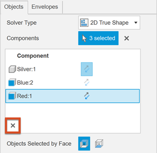
To remove one object, click it, then click
 in the lower left corner of the list.
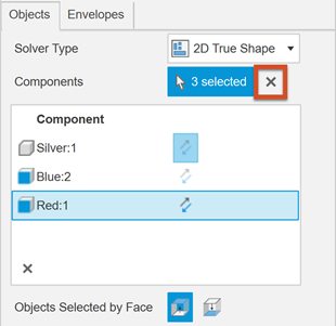
To remove all components, click
 next to the number of components selected.
(Optional) To apply the arrangement to copies of the selected components and keep the original ones in their respective locations, select the Create Copies checkbox.
Adjust component orientation
(Optional) You can flip the orientation of each individual component in the arrangement by clicking the Flip icon
 next to the component name.
(Optional) For all components selected by their faces, you can control their orientation globally by selecting Face Up
 or Face Down
  from the Objects Selected by Face options.
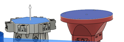
In the example below, the silver and red components are selected by their faces. By default, the selected face points upwards in the arrangement:
Changing the Objects Selected By Face option from Face Up
 to Face Down
  gives:
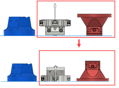
The blue component on the left is not affected because there was no face selection made on it.
(Optional) To allow fitting smaller components inside holes within larger ones, select the Allow Part-in-Part checkbox (2D True Shape Solver Type only).
Select area to arrange on
Switch to the Envelopes tab. With the Plane/Sketch/Face Select button active, click a plane, planar face, or sketch on which you want to arrange the components.
Fusion starts to calculate how to arrange the components you selected. If Auto Preview is selected, the arrangement is updated on the canvas.
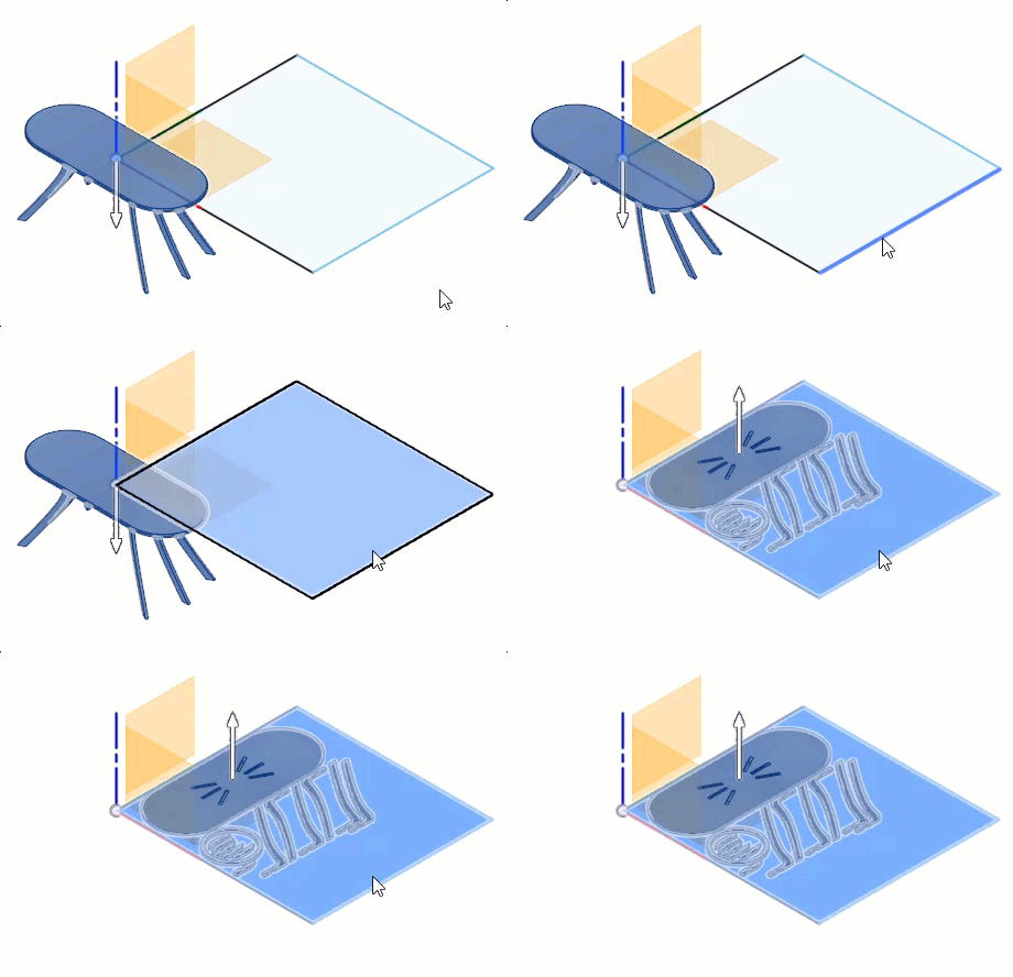
If you are arranging on a plane, the following boxes appear in the dialog:
- Length and Width - Sets the dimensions of the envelope along the X and Y axis.
- X Offset and Y Offset - Sets the point in which the envelope is created relative to the model origin.
(Optional) You can Allow Partial Arrange to still yield a result when there is not enough space on the envelope to fit all components. Components are arranged until all the available space is used up. The components that were not included in the partial arrangement are highlighted in the components list. If the envelope size increases, the arrangement recalculates to include the components that did not previously fit in the arrangement.
(Optional) Set the Placement Clearance value to specify the Z height of where the components are placed. A value of zero places the components directly on the selected plane, sketch, or face.
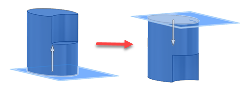
(Optional) To change the direction of placement on the plane or sketch, click Flip Envelope
 .
.
Set spacing values for components in your arrangement:
- Frame Width - Minimum distance between components and the boundary of the arrangement envelope.
- Object Spacing - Minimum distance between components inside the arrangement envelope. If the object spacing is set to 0, some shapes may produce arrangements with overlapping parts. In such scenarios, you can try a larger object spacing value or select a sketch that bounds a component when adding the component to the arrangement.
(Optional) If you find that the preview is taking too long to calculate, deselect Auto Preview and click Preview whenever you want to update the canvas.
Click OK to confirm.