Activity 4: Create dimensions
In this activity, you:
- Create linear, aligned, and diameter dimensions.
- Reposition dimensions.
- Use the baseline and chain dimensioning tools.
Prerequisites
- Activity 3 is complete.
Steps
Create a Linear Dimension.
Click Dimensions > Linear Dimension.
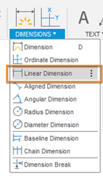
The Linear Dimension command is located under the Dimension drop-down list.
Use Object Snaps to click two endpoints on the bottom view (as shown in the image sequence below). A preview is displayed at your cursor location.
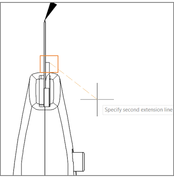
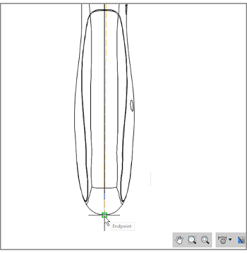
Object snaps.
Drag the cursor towards the right and click again to place the dimension.
A placed dimension.
Note: You can also press Spacebar and then select an edge to create a dimension with only one click.The command remains active to facilitate creating additional dimensions. Press
Escto terminate the Linear Dimension command.
Create an Aligned Dimension.
Click Dimensions > Aligned Dimension.
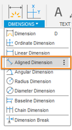
The Aligned Dimension command is located under the Dimension drop-down list.
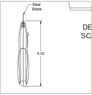
Using Object Snaps, click the top edge and bottom point of the cutting blade on the right view (as shown in the image below).
Drag the cursor out to the left to see a preview of the dimension.
Click again to place the dimension.
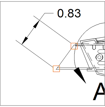
A placed dimension.
The command remains active to facilitate creating additional dimensions. Press
Escto terminate the Aligned Dimension command.
Reposition the Dimension.
Click the aligned dimension.
Click the gray grip on the text.
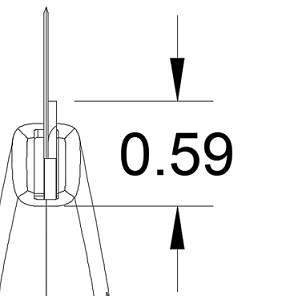
Move the text so it is between the dimension arrows.

Repositioning of the dimension.
Click anywhere outside the dimension to complete the action.
Create a Diameter Dimension.
Click Dimensions > Diameter Dimension.
Select the blade slider pin on the detail view.
Drag the cursor up and to the right and see a preview of the dimension.
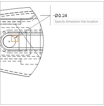
A diameter dimension.
Click again to place the dimension.
The command remains active to facilitate creating additional dimensions. Press
Escto terminate the Diameter Dimension command.
Steps for Using Chain and Baseline Dimensions
The Baseline Dimension tool creates multiple linear dimensions measured from the same location. The Chain Dimension tool creates multiple linear dimensions placed end to end.
Baseline and chain dimensions derive from an original dimension. You must first create a linear dimension before you create baseline or chain dimensions.
Create a new Linear Dimension.
Let's delete the Linear Dimension on the bottom view by selecting the dimension then pressing the Delete key, or by selecting Delete in the Marking Menu.
Create a new linear dimension at the end of the blade cradle.
A new linear dimension.
Place Chain Dimensions.
Click Dimensions > Chain Dimension.
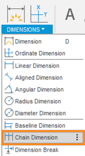
The Chain Dimension command is located under the Dimension drop-down list.
Select the lower extension line of the newly placed dimension.
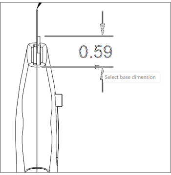
A chain dimension.
Complete the Chain Dimension.
Click the end of the knife's grip to specify the endpoint of the first dimension.
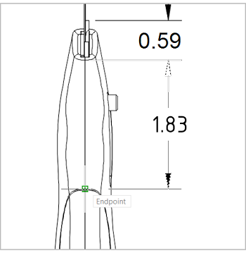
A chain dimension.
Click again to specify another endpoint of a dimension.
Click once more at the very end of the bottom view.
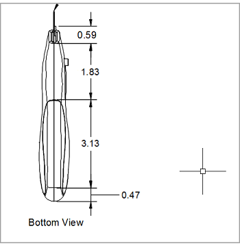
A chain dimension.
To finish the action, press
Enter.
Baseline Dimensions work the same way as Chain Dimensions, only they create multiple dimensions that all begin from the same location. If you had used the Baseline Dimensions here, it would have looked like this:
A baseline dimension.
Steps to Modify the Properties of an Individual Dimension, and add a Tolerance and Representation
Modify the Dimension's Properties.
Double-click the dimension on the back grip of the bottom view. The Dimension dialog displays.
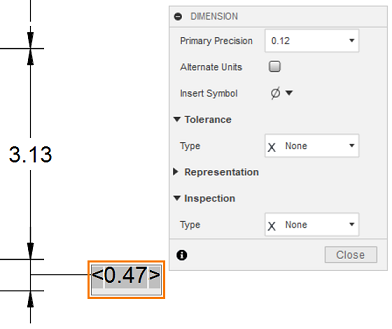
The dimension dialog.
In the Primary Precision field, choose 0.123 from the drop-down list.
Activate the Alternate Units option to display a dimension for an additional unit system.
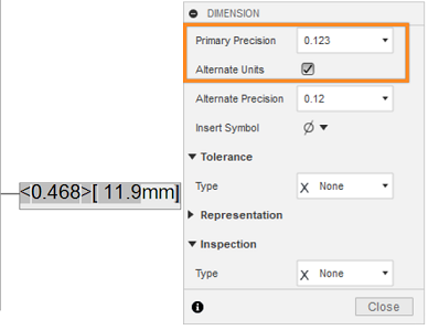
The dimension dialog.
Add Tolerance to the Dimension.
Choose Limit from the Type drop-down list in the Tolerance section of the dialog.
Ensure that both the Upper Tolerance and Lower Tolerance are set to 0.010.
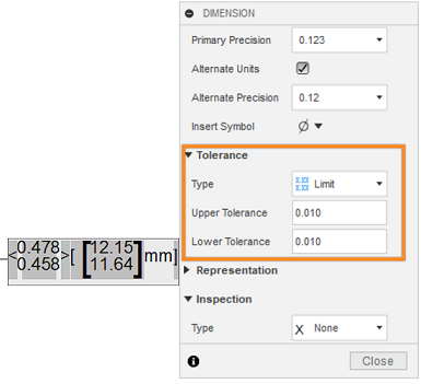
The dimension dialog.
Click Close.
Create a Reference Dimension.
Create a new linear dimension in the right view using the corner of the blade cradle and the quadrant snap point on the end of the handle as snap points.
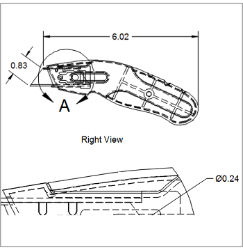
A reference dimension.
Press
Escto terminate the Linear Dimension command.Double-click the dimension you just created. The DIMENSION dialog appears.
Expand the Representation section of the dialog.
Select the Reference Dimension option under Representation.
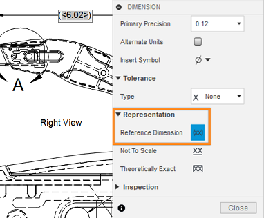
The dimension dialog.
Click Close.
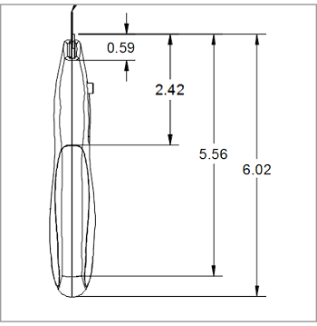
At this point, your drawing should look similar to the following image:
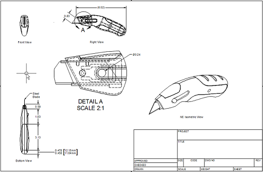
The Final look of the drawing by the end of Activity 4.
Activity 4 summary
In this activity, you:
- Created linear, aligned, and diameter dimensions.
- Repositioned dimensions.
- Used the baseline and chain dimensioning tools.
- Modified a dimension's properties.