Activity 4: Adding power
In this activity, you add power, voltage, ground, and terminal pins. Although the components on the board are wired together in the schematic, there is no power yet. The terminal pins will supply power from a battery to the board, enabling the circuit to function properly.
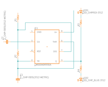
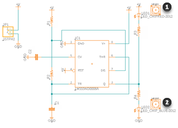
Circuit without power, ground, and voltage in the Schematic design.
Prerequisites
- Activity 3 is complete.
Steps
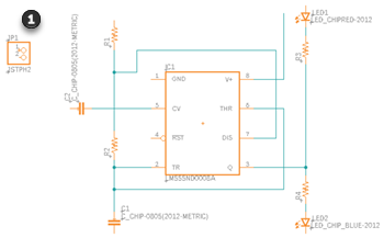
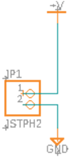
Add the battery connector, JSTPH2 to the schematic.
Click Design > Place > Place Component

In the Tutorial - Fusion library, double-click the JSTPH2 component and move the pointer on the canvas.
Position the battery connector in the location shown in the image below.
Click Done or press Esc to exit placement mode and return to the Place Components panel.
Add five grounds to the schematic.
In the Tutorial - Fusion library, double-click GND and move the pointer on the canvas.
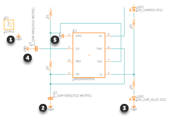
Position the five grounds in the locations shown in the image below. Rotate the symbol as necessary with a right-click.
After first placement, click OK to accept the name GND in Value dialog.
Click Done or press Esc to exit placement mode and return to the Place Components panel.
Add five voltage symbols to the schematic.
In the Tutorial - Fusion library, double-click +V and move the pointer on the canvas.
Position the five voltage symbols in the locations shown in the image below. Rotate the symbol as necessary with a right-click.
With first placement click OK to accept the name +V in Value dialog.
When prompted to change the name of a net, accept the name change.
Click Done or press Esc to exit placement mode and return to the Place Components panel.
Add two light pipes to the schematic.
In the Tutorial - Fusion library search for VLP.
Drag and drop VLP-300-R/F onto the canvas.
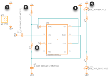
Position the two light pipes in the locations shown in the figure below.
Click Done or press Esc to exit placement mode and return to the Place Components panel.
Note: The light pipes are on the schematic but are not connected to anything. They are a mechanical component that is needed on the component when circuit board data is transferred to the PCB editor. The PCB editor is beyond the scope of this tutorial.
Add the nets between the pin head, ground, and voltage symbol.
Click Design > Connect > Net
 .
.Click Terminal 1 to the V+ symbol.
Click Terminal 2 to the GND symbol.
Activity 4 summary
In this activity, you defined how the circuit is going to get power, and where the voltage and grounds are.

Finished circuit in the Schematic design.