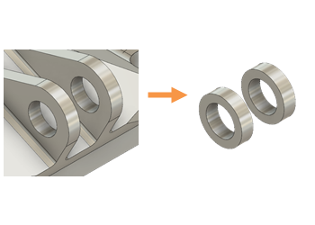
Create pin hole preserve geometry
It is critical for the generative solution that you define where you need geometry. When you have a starting model, you can define which parts you want to preserve, and which parts the generative solution can redesign. Pin holes, so assembly components can rotate relative to one another, are a good example of geometry that you may want to preserve.
You can use any of the tools in the Edit Model contextual environment of Generative Design to create your preserve geometry, such as Extrude ![]() as described in to create bolt hole preserve geometry. In this example, we create a surface copy of the inside of the pin hole, then use Thicken
as described in to create bolt hole preserve geometry. In this example, we create a surface copy of the inside of the pin hole, then use Thicken ![]() to increase its diameter.
to increase its diameter.

Tip: Remove unnecessary details, such as fillets or chamfers, to simplify the preserve geometry creation. Click on the unneeded feature and then press Delete on your keyboard.
- In the Generative Design workspace, on the Define tab, click Edit Model > Edit Model
 .
. - In the Edit Model contextual environment, on the Edit Model Surface tab, click Create > Offset
 .
. - Click on the inside face of each pin hole.
- In the Offset dialog, leave the Distance at 0 mm, confirm that the Operation is New Body, then click OK.
- Hide Body1 by clicking the Visible icon
 , to leave only the newly created surfaces.
 - On the Edit Model Surface tab, click Create > Thicken
 .
. - Click on each of the new center pin surfaces.
- In the Thicken dialog, enter a negative value for the Thickness, to ensure that the pin hole diameter does not decrease, and that the preserve geometry thickness is created in the direction of the starting model geometry.
- Confirm that the Operation is New Body, then click OK.
- Show Body1 by clicking the Visible icon
 .
.