Activity 3: Define the constraints and loads to be applied
In this activity, you create four load cases to test during the generative process.
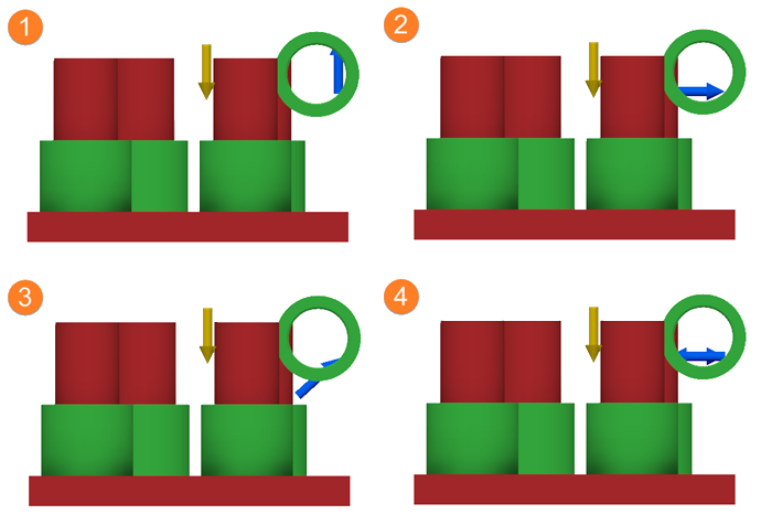
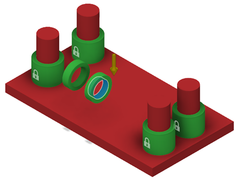
Finished examples of the four load cases.
Prerequisites
- The previous activity has been completed.
- The copy of the GE Bracket is open in the Generative Design workspace.
Steps
Apply a structural constraint to the external faces of the Fixed Constraints components.
- On the Define tab, click Design Conditions > Structural Constraints
 .
.
The Structural Constraints dialog opens. - In the dialog, ensure that Type is set to Fixed.
- In the design, select the faces highlighted in blue as shown in the following image.
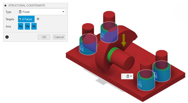
Note: The padlock icons on the selected faces indicated that the structural constraints have been applied. - In the Structural Constraints dialog, click OK.
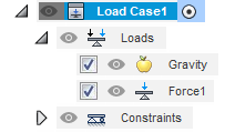
Warning: You can apply constraints to preserve geometries only. - To verify that the Fixed1 constraints have been applied, in the Browser, under Study 1 - Structural Component, expand Load Case1 > Constraints.
Tip: To modify the structural constraints, in the Browser, place the mouse pointer over Fixed1, and to the right, click the Edit icon
- On the Define tab, click Design Conditions > Structural Constraints
Apply a structural load to the internal faces of the Ring 1 and Ring 2 components.
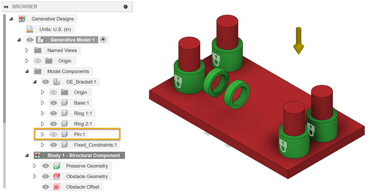
- To make it easier to define the first load case, in the Browser, under Model Components, to the left of Pin: 1, click the Visible icon
 .
.
- On the Define tab, click Design Conditions > Structural Loads
 .
.
The Structural Loads dialog opens. - In the dialog, verify that Type is set to Force.
- In the design, select the two, blue highlighted faces as shown in the following image.

- In the Structural Loads dialog, for Direction Type click the Vectors (x, y, z) icon
 .
. - In the Fz box, type 8000.
The blue, upward pointing arrows are shown on the selected faces.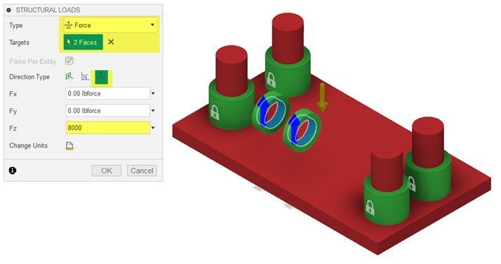
- Click OK.
- To verify that the force load is applied properly, in the Browser, under Study 1 - Structural Component, expand Load Case1 > Loads.
- To make it easier to define the first load case, in the Browser, under Model Components, to the left of Pin: 1, click the Visible icon
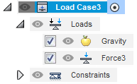
Clone Load Case1 three times.
- In the Browser, right-click Load Case1 and click Clone Load Case.
Load Case2 is created.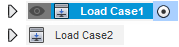
- Clone Load Case1 two more times for a total of four load cases.
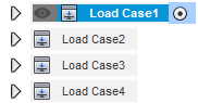
- In the Browser, right-click Load Case1 and click Clone Load Case.
Modify the Force2 load for Load Case 2.
- In the Browser, to activate it, double-click Load Case2.
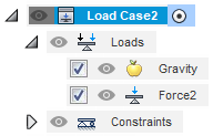
- If necessary, expand Loads.
- Place the mouse pointer over Force 2, and then click the Edit icon .
- In the Fy box, type -8500 and in the Fz box, type 0.
The arrows show on the selected faces as shown in the following image.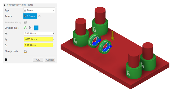
- Click OK.
- In the Browser, to activate it, double-click Load Case2.
Modify the Force3 load for Load Case 3.
- In the Browser, to activate and expand it, double-click Load Case3.
- Place the mouse pointer over Force 3, and then click the Edit icon .
- In the Fy box, type -7060 and in the Fz box, type 6357.
The arrows show on the selected faces as shown in the following image.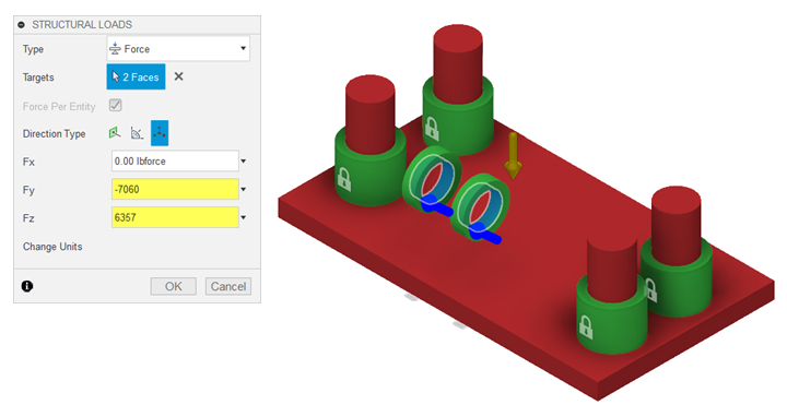
- Click OK.
- In the Browser, to activate and expand it, double-click Load Case3.
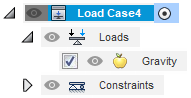
From Load Case4, delete Force4.
- In the Browser, to activate it, double-click Load Case4.
- If necessary, expand Loads.
- Right-click Force 4 and select Delete.
Apply a structural load to the internal face of the Ring 1 component.
- In the design, select the blue, highlighted face as shown in the following image.
- On the Define tab, click Design Conditions > Structural Loads .
The Structural Loads dialog opens. - In the dialog, verify that Type is set to Force.
- For Direction Type click the Vectors (x, y, z) icon .
- In the Fy box, type -1400.
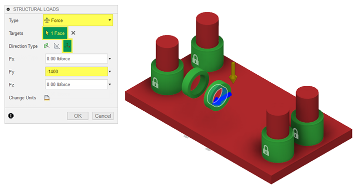
- Click OK.
In the Browser, under Load Case4 > Loads, Force5 is added.
- In the design, select the blue, highlighted face as shown in the following image.
Apply a structural load to the internal face of the Ring 2 component.
- In the design, select the blue, highlighted face as shown in the following image.
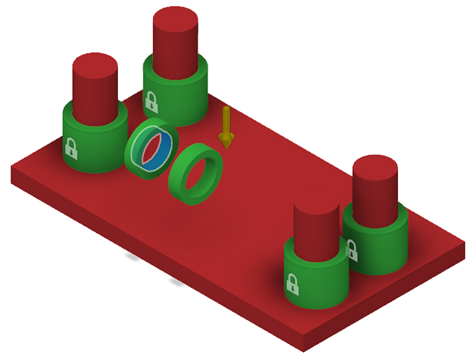
- On the Define tab, click Design Conditions > Structural Loads .
The Structural Loads dialog opens. - In the dialog, verify that Type is set to Force.
- For Direction Type click the Vectors (x, y, z) icon .
- In the Fy box, type 1400.

- Click OK.
In the Browser, under Load Case4 > Loads, Force6 is added.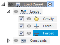
- In the design, select the blue, highlighted face as shown in the following image.
Verify the four load cases.
- On the ViewCube, click Front, then click the Left Arrow.
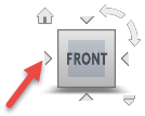
- In the Browser, double-click to activate each of the four load cases in order to verify that they match the following image.
- On the ViewCube, click Front, then click the Left Arrow.
Return the view to Home and show the Pin:1 component again.
- Place the mouse pointer over the ViewCube, and click the Home icon
 .
. - In the Browser, under Model Components, to the left of Pin:1, click the Hidden icon
 .
.
- Place the mouse pointer over the ViewCube, and click the Home icon
Activity 3 summary
In this activity, you applied four load cases to test during the generative process.