Activity 2: Specify manufacturing methods
In this activity, you specify the manufacturing constraints for all methods available in the product.
Prerequisites
- Activity 1 is complete.
Steps
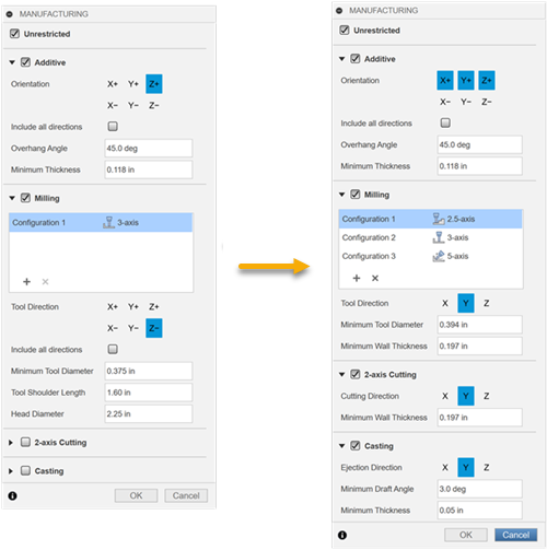
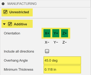
Specify the Unrestricted and Additive manufacturing methods for the generative study by applying the settings shown in the following image.
- On the Define tab, click Design Criteria > Manufacturing
 .
. - In the Manufacturing dialog, ensure that the Unrestricted and Additive methods are selected.
- Click X+, Y+, and Z+ buttons to set the 3D printing build direction for additive.
- For the Additive method, ensure that the default values are specified:
- In the Overhang Angle field 45.0 deg.
- In the Minimum Thickness field 0.118 in.
- On the Define tab, click Design Criteria > Manufacturing
Specify the 2.5-axis milling method to generate outcomes which can be subtractively manufactured using 2.5-axis milling operations by applying the settings shown in the following image.
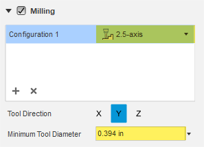
- In the Manufacturing dialog, ensure that the Milling method is selected.
- From the Configuration 1 drop-down menu, select 2.5-axis.
- Click Y button to set the tool direction for 2.5-axis machining.
Note: It orients the tool in the direction parallel to the Y axis of the triad. We will select this direction for all other methods. - In the Minimum Tool Diameter field, ensure that the default value is specified: 0.394 in.
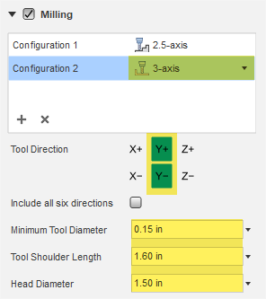
Specify the 3-axis milling method to generate outcomes which can be subtractively manufactured using 3-axis milling operations by applying the settings shown in the following image.
- To add a new milling configuration, in the Manufacturing dialog, click
 .
.
Note: By default, the 3-axis milling configuration is added. - Click Y+ and Y- buttons to set the tool direction for 3-axis machining.
Note: It orients the tool in the direction parallel to the Y axis of the triad and pointing to the positive/negative end of the Y axis. - Click Z- button to deselect the default direction.
- In the Minimum Tool Diameter field, enter 0.15 in.
- In the Tool Shoulder Length field, enter 1.60 in.
- In the Head Diameter field, enter 1.50 in.
- To add a new milling configuration, in the Manufacturing dialog, click
Specify the 5-axis milling method to generate outcomes which can be subtractively manufactured using 5-axis milling operations by applying the settings shown in the following image.
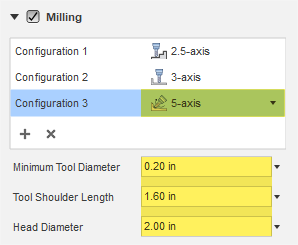
- To add a new milling configuration, click , and select the 5-axis option from the drop-down menu.
- In the Minimum Tool Diameter field, enter 0.20 in.
- In the Tool Shoulder Length field, enter 1.60 in.
- In the Head Diameter field, enter 2.00 in.
- To add a new milling configuration, click
Specify the 2-axis cutting method to generate outcomes which can be manufactured using 2-axis cutting operations by applying the settings shown in the following image.
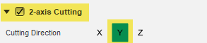
- In the Manufacturing dialog, ensure that the 2-axis Cutting method is selected.
- Click Y button to set the cutting direction.
Note: It orients the cutting tool in the direction parallel to the Y axis of the triad.
Specify the Casting method to generate outcomes that can be manufactured using the metal casting process by applying the settings shown in the following image.
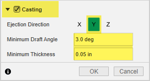
- In the Manufacturing dialog, ensure that the Casting method is selected.
- Click X and Z buttons to deselect X and Z directions.
- In the Minimum Draft Angle field, enter 3.00 deg.
- In the Minimum Thickness field, enter 0.05 in.
- Click OK.
Tip: To modify the specified manufacturing methods and constraints, mouse over the Manufacturing node in the Browser, and then click .
.
Activity 2 summary
In this activity, you specified the manufacturing constraints for all methods available in the product.