Workspaces
Switch between different Fusion workspaces, tabs, and contextual environments to access tools that suit your needs at each stage of your design process.
Workspaces in Fusion
Fusion capabilities are grouped into purpose-driven workspaces. The tools in each workspace are organized into tabs in the toolbar according to particular design objectives. Some tools are available across multiple workspaces.
Contextual tabs are tabs that only become active in context to the command you invoke. They are not visible until the command they are associated with is selected.
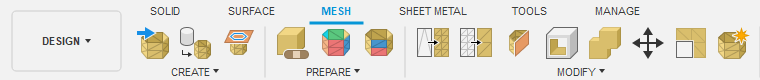
Design workspace
The Design workspace lets you create and edit solid, surface, and T-Spline model geometry, driven by 2D sketch geometry. This workspace is most like a traditional 3D CAD environment, where you can create history-based features (i.e. extrude, revolve, loft, sweep) that update with design changes.
Sketch contextual tab
![]() Sketch is a contextual tab that contains tools that let you create and modify 2D sketches that drive the 3D geometry of a design.
Sketch is a contextual tab that contains tools that let you create and modify 2D sketches that drive the 3D geometry of a design.
You can access the Sketch contextual tab in many areas in the Design workspace. The most common place is within the Solid tab > Create panel > Create Sketch.

Since you can create a Sketch within multiple tabs as well as contextual tabs, Sketch is a special case, and is shown with the other non-contextual tabs also visible.
Create Sketch reveals a new Sketch contextual tab with a dedicated toolbar that contains the most commonly used sketch tools in the toolbar by default. The sketch constraints are also visible in the toolbar by default. The tab itself is highlighted blue, as well as the Finish Sketch button, letting you know that you are currently in a temporary mode.
The difference between the Sketch contextual tab and other contextual tabs is that you are still able to go to other tabs while the Sketch tab is active. This is because you’re able to invoke modeling commands (for example, Extrude) even when your sketch is active. Doing so will automatically take you out of Sketch mode and into the command itself.
Learn more about the Sketch tools.
Solid tab
The Solid tab contains tools that let you create and modify solid models.

Learn more about the solid modeling tools.
Form contextual environment
![]() Form is a contextual environment that lets you push and pull faces, edges, and vertices on T-Spline bodies to create complex organic feature. The tools are similar to sculpting clay.
Form is a contextual environment that lets you push and pull faces, edges, and vertices on T-Spline bodies to create complex organic feature. The tools are similar to sculpting clay.
You can access the Form contextual environment from the Solid tab, Create panel.

Learn more about the T-Spline form tools.
Surface tab
The Surface tab contains tools that let you create and modify complex parametric surfaces. Surfaces represent the outer shape of a design, but have no thickness. You can also use the tools on the Surface tab to patch or repair openings in a model.

Learn more about the Surface modeling tools.
Mesh tab
The Mesh tab contains tools that let you create and modify parametric mesh bodies. A mesh body is a collection of polygon faces composed of vertices and edges. A mesh has no thickness. Meshes are commonly used in additive manufacturing.
You can use the Mesh commands to insert, repair, and modify mesh bodies to prepare them for manufacturing.
Learn more about the Mesh modeling tools.
Sheet Metal tab
The Sheet Metal tab contains tools that let you create and modify Sheet Metal components using sheet metal rules. You can document and manufacture flat patterns using 2D drawings and cutting strategies.

Learn more about the Sheet Metal tools.
Flat Pattern contextual environment
![]() Flat Pattern is a contextual environment that lets you create a Sheet Metal flat pattern from a folded design.
Flat Pattern is a contextual environment that lets you create a Sheet Metal flat pattern from a folded design.
You can access the Flat Pattern contextual environment from the Sheet Metal tab, Create panel.
Flat Pattern Solid tab: Use the tools on the Flat Pattern Solid tab to create and modify Flat Patterns with solid geometry.

Flat Pattern Surface tab: Use the tools on the Flat Pattern Surface tab to create and modify Flat Patterns with surface geometry.

Base Feature contextual environment
![]() Base Feature is a contextual environment that lets you enter a direct modeling sandbox and inserts a history-free feature in the Timeline. Base feature gives you access to both modeling and surfacing tools.
Base Feature is a contextual environment that lets you enter a direct modeling sandbox and inserts a history-free feature in the Timeline. Base feature gives you access to both modeling and surfacing tools.
You can access the Base Feature contextual environment from the Solid tab, Create panel.
Learn more about the Base Feature contextual environment.
Base Feature Solid tab: Use the tools on the Base Feature Solid tab to create and modify solid geometry.

Base Feature Surface tab: Use the tools on the Base Feature Surface tab to create and modify surface geometry.

Electronics
The Electronics environment lets you create and edit schematics, 2D PCB layouts, 3D PCB designs, electronic components, and component libraries. You can leverage a shared component library between Fusion and EAGLE, and link components between the two so that updating changes all happen seamlessly.
Electronics Design
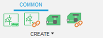
You access the Electronics Design environment from the File menu, New Electronics Design. In the Common tab you begin the design process by selecting to create or reference a schematic or pcb design.
The Schematic Design tab contains tools that let you create and edit your electronic design schematics. Add components from libraries, set the values and arrange them. Connect components with nets and use buses in your schematic and simulate your design.

The Schematic Document tab contains tools that give you access to assembly variants and the bill of materials. Drawing tools allow you to do some artwork in your schematics. It also gives access to attributes of components.

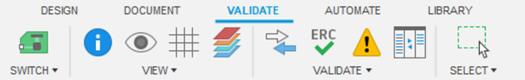
The Schematic Validate tab contains tools that let you define net classes, execute an electrical rule check, and synchronize your schematic with the 2D PCB in case you lost consistency between schematic and 2D PCB.
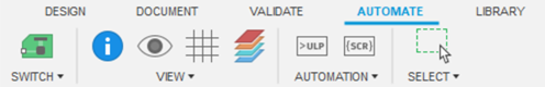
The Schematic Automate tab contains tools that let you execute command scripts and User Language Programs.
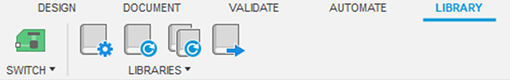
The Schematic Library tab gives you access to the Library Manager to navigate your libraries. Update components in your design with newer versions from the libraries or export the components used in your design into libraries.
The 2D PCB Design tab contains tools that let you create and edit your printed circuit board design. It gives access to various routing tools to layout the signals in the board.

The 2D PCB Document tab contains tools that let you specify names, values and attributes for components and tools for drawing some artwork and adding dimensions to your layout.

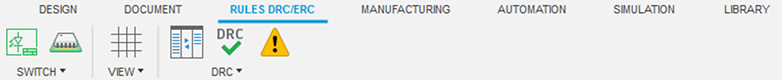
The 2D PCB Rules tab gives access to the Design Rules Check. This tool let you set design rules and validate your design against them.
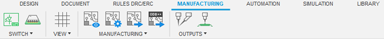
The 2D PCB Manufacturing tab contains tools that allow you to create manufacturing data for your PCB design. Preview the output first or start the CAM Processor to create a full set of manufacturing data (Gerber, drill, ODB++, Bill of Materials, Pick&Place, PDF).
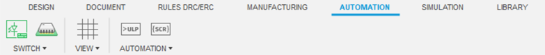
The 2D PCB Automation tab contains tools that let you execute command scripts and User Language Programs.
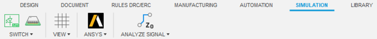
The 2D PCB Simulation tab provides access to ANSYS simulation tools. Simulate electronics design performance and spatial relationships in order to keep the electronic designs operating at their best.
The 2D PCB Library tab provide access to you the Library Manager to navigate your component libraries. From here update component definitions in your design from updated libraries.

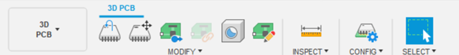
The 3D PCB tab contains tools that let you orient components, add through holes, modify the pcb shape. You can push the changes back to the 2D PCB design so no change is lost or forgotten.
Electronics Library
The Electronics Library lets you create and edit electronic devices, symbols, footprints, 3D packages, and component libraries. You can create completely new devices or reference already existing devices on which to base your design.
You access the Electronics Library environment from the File menu, New Electronics Library. You begin by choosing to create or import a component, symbol, footprint, or 3D package.
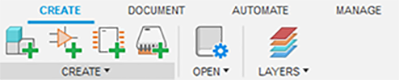
The Device tab contains tools that let you create and edit electronic components.

The Symbol tab contains tools that let you create and edit electronic component symbols.

The Footprint tab contains tools that let you create and edit electronic component footprints.

The Package 3D tab contains tools that let you create and edit 3D models for your electronic components.

The Document tab contains tools that let you access the library manager, view layers, and print your electronic component designs.
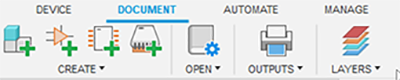
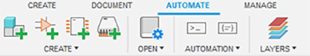
The Automate tab contains tools that let you execute command scripts and User Language Programs.
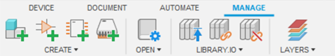
The Manage tab gives you access to the Library Manager where you can navigate to your libraries, update components with newer versions from the libraries or export the components used in your design into libraries.
Learn more about the Electronics environment.
Generative Design workspace
The Generative Design workspace lets you simultaneously generate multiple CAD-ready design solutions based on manufacturing and performance requirements.
Learn more about the Generative Design workspace.
Define tab
The Define tab contains tools that let you set up design studies with defined goals, constraints, materials, and manufacturing options. Generate multiple process- and performance-aware design options in the cloud using tokens. Explore and evaluate each design option based on tradeoffs that are most critical to your needs. Then export your optimal design and import the CAD-ready geometry into Fusion.

Edit Model contextual environment
![]() The Edit Model contextual environment lets you use standard Fusion modeling tools to create and edit model geometry and create obstacle and preserve geometry.
The Edit Model contextual environment lets you use standard Fusion modeling tools to create and edit model geometry and create obstacle and preserve geometry.
You can access the Edit Model contextual environment from the Define tab, Edit Model panel.
Edit Model Solid tab: The Edit Model Solid tab contains tools that let you edit solid model geometry without leaving the Generative Design workspace.

Edit Model Surface tab: The Edit Model Surface tab contains tools that let you edit surface model geometry without leaving the Generative Design workspace.

Explore contextual environment
![]() The Explore contextual environment lets you display the model, stress, export preview, and design space views of an outcome. You can also open the Comparison View.
The Explore contextual environment lets you display the model, stress, export preview, and design space views of an outcome. You can also open the Comparison View.
You can access the Explore contextual environment from the Define tab, Explore panel.
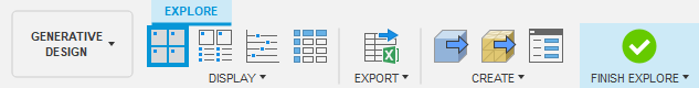
Outcome View contextual tab: Within the Explore contextual environment, when you select one or more outcomes to explore in the 3D View or Comparison View, the toolbar switches to the Outcome View contextual tab, which includes different tools to display, compare, and export outcomes.

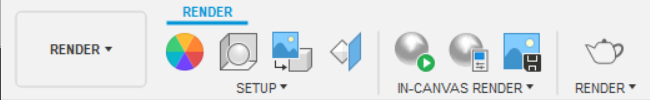
Render workspace
The Render workspace lets you generate photo-realistic images of your design. Adjust lighting and materials, add decals, and leverage local or cloud computing to communicate your design realistically.
Learn more about the Render workspace.
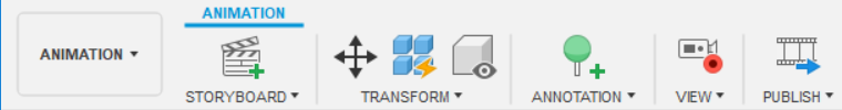
Animation workspace
The Animation workspace helps you communicate your design with 3D exploded views and animations to show design assembly. Share videos with collaborators and clients to help them understand and evaluate your design.
Learn more about the Animation workspace.
Simulation workspace
The Simulation workspace lets you set up studies to test your design using finite element analysis (FEA). Simulate how your design performs under various loads and conditions. Analyze the results to understand the physical limitations of your design. Explore design alternatives and make informed decisions about design changes.
Learn more about the Simulation workspace.
Setup tab
The Setup tab is active by default. It contains tools that let you setup a Simulation.

Results tab
The Results tab contains tools that let you analyze Simulation results.

Simplify contextual environment
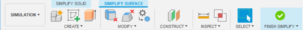
![]() The Simplify contextual environment lets you make simulation-specific modifications to the model geometry. These changes have no effect on the production geometry created in the modeling workspaces.
The Simplify contextual environment lets you make simulation-specific modifications to the model geometry. These changes have no effect on the production geometry created in the modeling workspaces.
You can access the Simplify contextual environment from the Setup tab, Simplify panel.
Learn more about the Simplify contextual environment.
Simplify Solid tab: The Simplify Solid tab contains tools that let you make simulation-specific edits to solid model geometry.

Simplify Surface tab: The Simplify Surface tab contains tools that let you make simulation-specific edits to surface model geometry.
Compare contextual environment
The Compare contextual environment lets you compare simulation results. It becomes available after a Simulation study completes successfully and results are available to view. Use the Compare contextual environment to look at various simulation study results in side-by-side windows.
You can access the Compare contextual environment from the Results tab, Compare panel.
Learn more about the Compare contextual environment.
Manufacture workspace
The Manufacture workspace lets you create toolpaths to produce your components using processes such as machining and turning (subtractive manufacturing) or 3D printing (additive manufacturing).
Learn more about the Manufacture workspace.
Milling tab
The Milling tab contains tools related to 2D milling, 3D milling, drilling, and multi-axis machining.

Turning tab
The Turning tab contains tools related to turning and drilling.

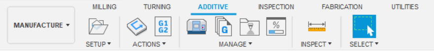
Additive tab
The Additive tab contains tools related to additive manufacturing.
Inspection tab
The Inspection tab contains tools to help you use probing to verify that your part is set up correctly on your machine and is produced to specified tolerances.

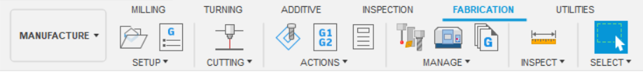
Fabrication tab
The Fabrication tab contains tools related to cutting.
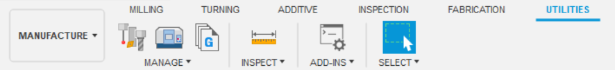
Utilities tab
The Utilities tab contains tools related to the Tool Library, Task Manager, inspection, and add-ins.
Drawing workspace
The Drawing workspace lets you document manufacturing specifications using integrated, associative drawings and animations for parts and assemblies.

Learn more about the Drawing workspace.
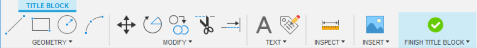
Title Block contextual environment
The Title Block contextual environment lets you modify the title block. You can add attributes, text, basic geometry, and images.
To access the Title Block contextual environment, select the title block on the current sheet, right-click, then click Edit Title Block.
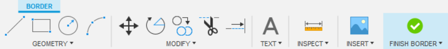
Border contextual environment
The Border contextual environment lets you modify the title block and border. You can add text, basic geometry, and images.
To access the Border contextual environment, select the border on the current sheet, right-click, then click Edit Border.