Sheet metal flat patterns
Use the Flat Pattern ![]() tool to create a flat pattern that you can use to create drawings of a sheet metal component for manufacturing in Fusion.
tool to create a flat pattern that you can use to create drawings of a sheet metal component for manufacturing in Fusion.
A Flat Pattern is the shape of the sheet metal component before it is formed.
| Folded sheet metal body | Flat pattern view |
|---|---|
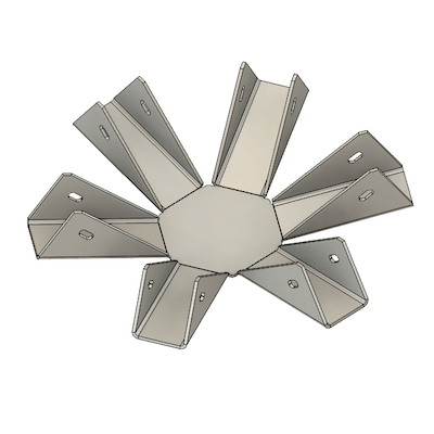 |
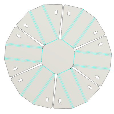 |
Flat patterns show bend lines, bend zones, center lines, and the shape of the entire sheet metal body with all bends flattened and bend factors considered.
After you create a flat pattern, a Flat Pattern node is created in the Browser. You can switch between the folded state and the flat pattern state with the Activate Flat Pattern radio button.
A new folder under the Bodies browser node is created containing bend lines and center lines. It will be visible when Flat Pattern mode is active.
The flat pattern has its own timeline. The first feature is the creation of the flat pattern and reflects the current version of the 3d model. Any changes made to the original 3d model can be pushed to the flat pattern by updating the linked flat pattern.

When in the Flat Pattern environment you can make additional changes to the flat pattern. These changes will not affect the folded model. Use this to model additional features for manufacturing, such as tabs.
Unfold vs flat pattern
Flat pattern is not the same as Unfold (the temporary flattened preview you use with Modify > Unfold and Refold).
Unfold keeps relief shapes consistent with the folded sheet metal body because the model must refold to the same 3D result. That round-trip stays geometrically simple; it does not apply every relief variation used for cutting.
Flat pattern is a derived flat representation for manufacturing. It resolves relief shapes and related cut geometry according to your settings so the flat shows how the part will actually be cut, including reliefs that are not shown the same way in folded or unfolded design views. Design changes in the folded 3D model can be carried into the flat pattern when you update it, but not the other way around. Edit in the flat pattern can't be used to update folder model.
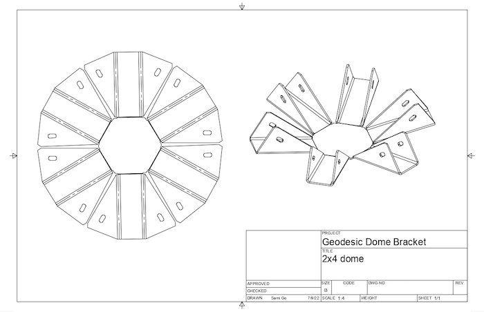
Drawings of flat patterns
You can create drawings from flat patterns. The flat pattern contains a wealth of bend and punch information useful for the creation of manufacturing drawings.
The folded sheet metal body can be added to the same sheet as well. If you delete the flat pattern, that view will be lost.
Create a drawing view of the flat pattern directly when you have the flat pattern activated.
When your design contains components, you can create a drawing that contains flat pattern and a folded design in the same sheet, using the Create Drawing tool accessible from the right-click menu from the activated component.
Tips
- You can create one flat pattern per sheet metal component.
- Flat patterns do not support all the distributed designs workflows.
- Use a flat pattern to calculate more accurate mass and volume data. Use the folded view to calculate the moment of inertia data.
- Use Flat Pattern, rather than Unfold, to create drawings of flattened sheet metal components.
- Export the flat pattern as a DXF for use in different manufacturing methods such as laser or water jet cutting.