Base/edge/contour flange reference
The Flange ![]() creates a sheet metal flat or bend flange based on sketch profiles you select in Fusion.
creates a sheet metal flat or bend flange based on sketch profiles you select in Fusion.
Design > Sheet Metal > Create > Flange (Base/Edge/Contour) ![]()
Type
Base Flange
 : Creates a flat sheet metal body from a closed sketch profile.
Edge Flange
 : Extends selected sheet metal edges to create flanges at the specified angle and height.
Contour Flange
 : Creates a sheet metal flange with multiple bends from an open sketch profile that can consist of lines, arcs, or splines. You can also join a contour flange to an existing sheet metal edge.
Selection box
Each line in the selection box represents a different flange profile.
Adjust the following for each row independently:
+: Add a selection set to the list.
X: Remove the highlighted selection set from the list.
Flange Width Type for Edge flange type:
Full Edge
 : Creates a flange along the entire length of the selected edge.
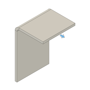
Symmetric
 : Creates a flange of a specified distance centered on the mid-point of the selected edge.
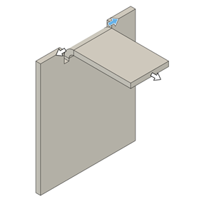
- Distance: Specifies the overall distance of the flange, centered on the mid-point of the selected edge.
Two Sides
 : Creates a flange centered on the mid-point of the selected edge with two adjustable width extents on both sides.
- Distance 1: Specifies the distance to extend one side of the flange from the mid-point of selected edge.
- Distance 2: Specifies the distance to extend other side of the flange from the mid-point of selected edge.
Two Offsets
 : Creates a flange positioned between two selected reference faces, with adjustable offsets from each face.
- Reference 1: Select a face, point, or plane to define the reference for one side's offset.
- Offset 1: Specifies the distance from Reference 1 to extend the flange on one side.
- Reference 2: Select a face, point, or plane to define the reference for the other side's offset.
- Offset 2: Specifies the distance from Reference 2 to extend the flange on other side.
Edges/Profiles
Select sheet metal edges or sketch profiles to create base, edge, or contour flange.
Extent Type (Edge flange type)
Specifies how the edge flange extends from the selected edge.
Distance (default): Specifies the height to extrude the flange from the height datum. You can drag the distance handle on the canvas or specify an exact value.
- Height Specifies the distance to extrude the flange from the height datum.
To Object: Extends the flange until it meets a selected face, plane, or body. This option is only available when you select a single edge, as multiple edges can extend in different directions and Fusion cannot determine where to extend. The target object must be planar (cannot be round or curved) and must lie on a plane that is parallel to the edge being extended.
Object: Select a face, plane, or point to extend the flange to.
Offset: Value to offset the flange from the selected target object.
Height: Indicates that flange height is determined by the distance to the selected object.
Angle (Edge flange type)
Specifies the angle of the flange limited by plane of selected object.
Height Datum (Edge flange type)
Controls where the flange height is measured from.
Inner Faces
 : Sets the height reference to the intersection on the inner faces of the base flange and the new flange.
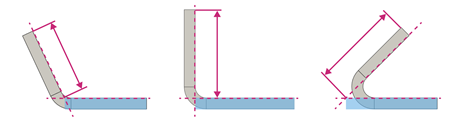
Outer Faces
 : Sets the height reference to the intersection on the outer faces of the base flange and the new flange.
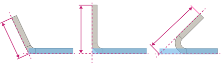
Tangent To Bend
 : Sets the height reference tangent to the bend between the base flange and new flange, parallel to the new flange.
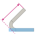
Bend Position (Edge flange type)
Controls where the bend is positioned between the base flange and the new flange.
Inside
 : Places the bend inward, so it starts inside the outer edges of the base and new flange.
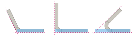
Outside
 : Places the bend so it extends beyond the inner edges of the base and new flange.
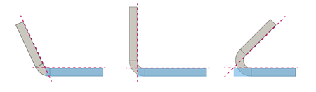
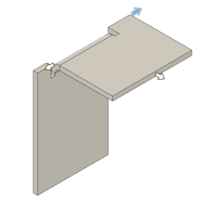
Adjacent
 : Places the bend so that it starts at the selected edge on the flange.
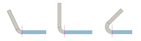
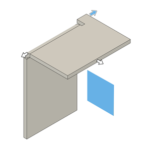
Tangent
 : Places the bend so that it is tangent to the selected edge on the flange.
Flip (Edge flange type)
Flip ![]() flips the new flange 180 degrees over the base flange.
flips the new flange 180 degrees over the base flange.
Miter Corners (Edge flange type)
Miters the corners where sheet metal corners would otherwise overlap.
Orientation (Base and Contour flange types)
Orients the sheet metal material relative to the selected sketch profile.
- Side 1
 : Extrudes sheet metal material to one side of the sketch profile.
 - Side 2
 : Extrudes sheet metal material to the opposite side of the sketch profile.
 - Center
 : Extrudes sheet metal material evenly on both sides of the sketch profile.
Operation (Base and Contour flange types)
Creates a separate sheet metal body or component within the same design.
- New Body
 : Creates a separate sheet metal body within the active component. The new body appears in the Browser, nested in the Bodies folder of the active component.
 - New Component
 : Creates a new sheet metal body in a separate component.
Direction (Contour flange type)
Controls the direction that sheet metal flange is extruded from the sketch profile.
One Side
 : Extrudes flange on one side of the profile plane.
Two Sides
 : Extrudes flange unevenly on each side of the profile plane.
Symmetric
 : Extrudes flange evenly on both sides of the profile plane.
Sheet Metal Rule
Shows the list of rules available in the design. This option appears when you create the first sheet metal body in a component that does not have a Sheet Metal Rule assigned.
Select a rule from the list to assign it to the component when the flange is created. If you do not select a rule at this point, Fusion assigns the default one. You will need to change the sheet metal rule later in the Browser.
Override Rules
Changes specific setting values for the new flange.
Select to apply custom values or deselect to use the Sheet Metal Rule defaults.
Bend Override
Overrides the bend radius value for the new flange. Select to apply custom value or deselect to use the Sheet Metal Rule default.
For all available bend condition shapes and options, see Bend conditions in the Sheet metal rule reference.
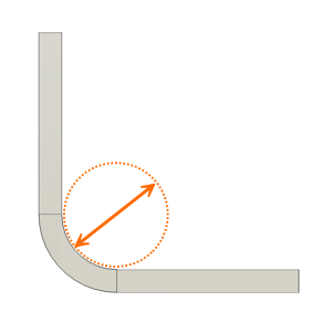
- Bend Radius: Specifies a distance from the inner surface of the sheet to the center of the bend. This controls how tightly the material bends and affects both strength and appearance.
Bend Relief Override
Overrides the relief shape, width, depth, and remnant values of bends for the new flange.
Select to apply overrides. Deselect to restore the values defined in the Sheet Metal Rule.
For all available bend condition shapes and options, see Bend conditions in the Sheet metal rule reference.
2-Bend Corner Override
Overrides the relief shape, size, and placement at corners where two bends intersect.
Select to apply overrides. Deselect to restore the values defined in the Sheet Metal Rule.
For all available 2-bend corner relief shapes and options, see 2 Bend corner relief type and size in the Sheet metal rule reference.
3 Bend Corner Override
Overrides the relief shape and radius at corners where three bends intersect.
Select to apply overrides. Deselect to restore the values defined in the Sheet Metal Rule.
For all available 3-bend corner relief shapes and options, see 3 Bend corner relief type and size in the Sheet metal rule reference.