Activity 5: Create and run a second study with different loads and constraints
In this activity, you create a new study, Study 2 - Static Stress with different constraints and loads. To change the constraints and loads, and run the analysis, you
- Activate Remove rigid body modes, to prevent free-body motion
- Delete the fully fixed constraint that was applied to the small pin. It is OK that the Y and Z constraints remain, because no applied loads act in the Y or Z directions
- Apply a load to the small pin in the opposing direction to the load that exists on the large pin
- Run the analysis.

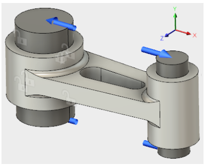
Connecting Rod assembly, partially constrained, with load applied.
Prerequisties
- Activity 4 is complete.
Steps
Clone Study 1, and activate Remove rigid body modes in the newly created Study 2.
- In the browser, right-click Study 1 - Static Stress and select Clone Study from the context menu.
A Study 2 - Static Stress node appears in the browser, and the new study becomes the active one. - Click
 (Simulation workspace > Setup tab > Manage panel > Settings) to open the Settings dialog.
 - In the General section, select Remove rigid body modes to activate it.
- Click OK to accept the changes and close the dialog.
- In the browser, right-click Study 1 - Static Stress and select Clone Study from the context menu.
Delete the fully fixed constraint that you applied to the small pin when you created Study 1.
- In the Browser, expand the Load Case:1 branch of Study 2.
- Expand the
 Constraints subbranch under Load Case: 1.
 - Right-click
 Fixed1 under Constraints, then click
  Delete from the context menu.
Note: With this constraint removed, there is now no X constraint anywhere on the model. In the next step, you balance the X loads applied to the model.
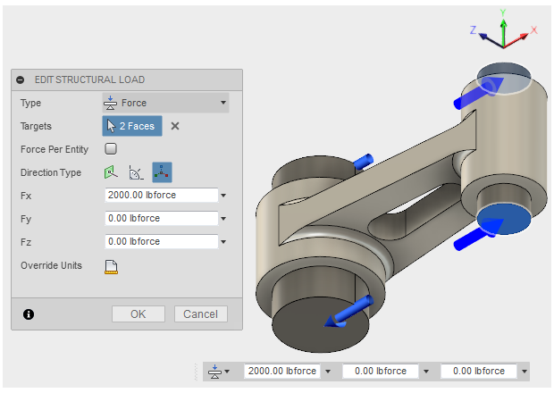
Apply a 2,000 pound force load to the small pin, that is equal to the large pin load but acting in the opposite direction.
- Click
 (Simulation workspace > Setup tab > Loads panel > Structural Loads) to open the Structural Loads dialog.
 - Click the top (+Y) end face of the small pin to select it, then rotate the model, and click the bottom (-Y) end face of the small pin to select it too.
- In the Structural Loads dialog, confirm that the load Type is Force, then set the Direction Type to
 Vectors (x, y, z).
 - Type 2000 in the Fx input field.

- Click OK to accept the changes and close the dialog.
- Click
 Home to return the model to its default isometric rotation.
- Click
Check the simulation setup to confirm it is ready to be solved.
The Pre-check icon in the Solve panel of the Simulation toolbar shows an orange exclamation point
 , indicating that there is a warning.
- Click
 for details.
The warning indicates that no structural constraints are defined. We expect this warning because we are relying on Remove rigid body modes to stabilize the model, instead of constraints. - Click Close to dismiss the warnings.
- Click
Solve the study.
- Click
 (Simulation workspace > Setup tab > Solve panel > Solve), to open the Solve dialog.
 - Confirm that Simulation Model 1 - Study 2 - Static Stress is selected, then click Solve to run the analysis.
Note: This model may take several minutes to solve. The solution must be performed iteratively multiple times. The solver has to determine at what points along the contact faces the model is touching and where it is separating. - When the analysis is complete, click Close to close the Job Status dialog and view the results.
- Click
Activity 5 summary
In this activity, you
- Activated Remove rigid body modes, to prevent free-body motion
- Deleted the fully fixed constraint that was applied to the small pin
- Applied a load to the small pin, acting in the opposite direction from the load on the large pin
- Ran the analysis.