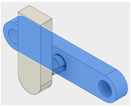
Activity 2: Make the stationary body rigid and select a material
In this activity, you declare the stationary female part a Rigid Body and select a different material for the analysis. We are not concerned with the stresses in the female part. The critical stresses are at the locking fingers of the male part. Rigid parts can translate or rotate, but they cannot deform, and no strains or stresses are calculated for them.
In this activity you
- Declare a Rigid Body to reduce the solution time of the simulation
- Change the material for the Simulation model to a stronger one
Prerequisites
- Activity 1 is complete.
Steps
Declare the female body, with three holes, a Rigid Body.
Click
 (Simulation workspace > Setup tab > Rigid Bodies panel > Rigid Bodies) to open the Rigid Bodies dialog.
Click the body that has three holes to select it as the Target.

Click OK to accept the selection and close the Rigid Bodies dialog.
Select Nylon 6/6 as the material for both bodies in the Simulation model.
Note: Both pieces of the snap-fit assembly have been designed using ABS plastic. A simulation of this material would reveal that it is not strong enough to withstand the stresses developed during assembly. Nylon 6/6 is stiffer than ABS plastic, which increases stresses, but it is also about four times stronger.Click
 (Simulation workspace > Setup tab > Materials panel > Study Materials) to open the Study Materials dialog.
Click in the first row to select the first component.
Holding down the Ctrl key, click in the second row to select this component too.
Note: The table header turns blue to indicate multiple rows have been selected.Hover over either entry in the Override column and click
 Edit to activate the drop-down menu.
Click the down arrow to open the drop-down menu and select Nylon 6/6. Notice that the material in the other row does not change. All selected rows update when you click OK
Click OK to accept the selection and apply it to both selected rows.
Activity 2 summary
In this activity, you
- Declared the female part a Rigid Body to reduce the solution time of the simulation
- Changed the material for the Simulation model to Nylon 6/6.