Activity 3: Apply constraints
In this activity you fully constrain the rigid body and apply a prescribed translation to the moving part, enabling it to move in the -Z direction while preventing motion in the X and Y directions. To constrain the model you
- Apply fixed structural constraints to the rigid body
- Define the face on which to apply the presribed translation
- Apply a prescribed translation to the moving part
- Define the multiplier curve that controls the prescribed translation.
Prerequisites
- Activity 2 is complete.
Steps
Fully fix the rigid body in all six translational and rotational degrees of freedom.
Click
 (Simulation workspace > Setup tab > Constraints panel > Structural Constraints), to open the Structural Constraints dialog.
Confirm the constraint Type is set to Fixed.
Click the female part to select it as the Target.
Note: Since it is a rigid body, the entire body is selected when you click any edge or face.Notice that three rotational degrees of freedom (DOF) appear in the Structural Constraints dialog in addition to the usual translational DOF. Elements belonging to rigid bodies support six DOF.
Confirm that the Ux, Uy, Uz, Rx, Ry, and Rz Axis options are all activated, as indicated by blue highlighting.
Click OK to set the constraints and close the dialog.
Define the front face of the moving part as the location to apply a Prescribed Translation.
Note: In Fusion, prescribed translations are considered to be constraints rather than loads because they control the position of an object. This translation pushes the parts together.Click
 (Simulation workspace > Setup tab > Constraints panel > Prescribed Translation) to open the Prescribed Translation dialog.
Confirm that the Object Type is set to
 Faces.
Ensure that the Constraint Type is set to Displacement.
Click the front face of the moving part to identify it as the Selection.
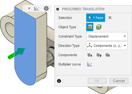
Apply a Prescribed Translation of 10 mm in the -Z direction to the front face of the moving part.
Confirm that the Direction Type is set to Components (x, y, z).
Click on all three Components, Ux, Uy, and Uz to select them.
Note: To prevent X and Y motion without applying a separate fixed constraint, select Ux and Uy but leave the magnitude at zero.Enter a value of -10 mm in the Magnitude Uz field.
Define the Multiplier Curve that controls the prescribed translation using the values shown in the image below:
In the Prescribed Translation dialog, click
 Multiplier curve.
Enter the Time and Multiplier data points shown in the following image:
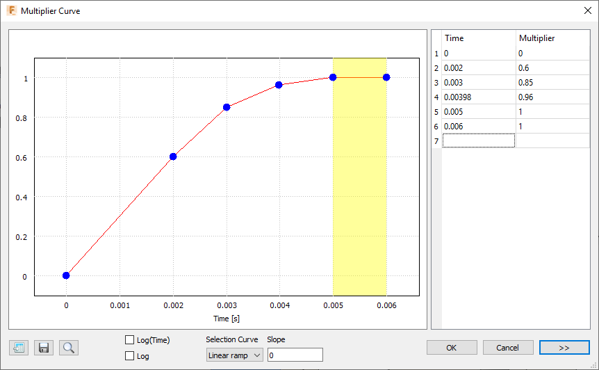 Note: This curve gradually decelerates the displacement as the end of the event is approached. Then, the position is held constant for an additional millisecond, during which you will see any bending oscillations that continue after insertion at the locking fingers of the snap fit assembly. The first two data points indicate a velocity of 3,000 mm/second (0.6 * 10 mm / 0.002 s). In the next procedure, we apply an initial velocity to this part to prevent the shock of a sudden acceleration from zero to 3,000 mm/second.
Click OK to accept the curve.
Click OK to apply the prescribed translation and close the dialog.
Activity 3 summary
In this activity, you
- Applied fixed structural constraints to the rigid body
- Defined the front face of the moving part as the location to apply the presribed translation
- Applied a prescribed translation to the moving part
- Defined the multiplier curve that controls the prescribed translation.