Activity 3: Complete the simulation setup and solve the study
In this activity, you complete the analysis setup by applying a load. You define the separation contact wherever parts, or the connecting rod assembly, are touching each other, to allow the bodies to slide along each other. You then run the analysis.
To complete the study setup and run the analysis, you
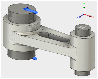
- Apply a 2,000 pound force load equally divided between the end faces of the large pin
- Use Automatic Contacts to find the contact sets, then manually change from the default contact type, Bonded, to Separation
- Run the analysis

Connecting Rod assembly, fully constrained, with load applied.
Prerequisties
- Activity 2 is complete.
Steps
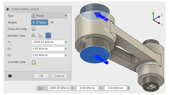
Apply a total force of 2,000 pounds in the -X direction to the end faces of the large pin (1,000 pounds per end).
- Click
 (Simulation workspace > Setup tab > Loads panel > Structural Loads) to open the Structural Loads dialog.
 - In the Structural Loads dialog, confirm that Type is set to
 Force.
 - Click the top face of the large pin to select it as a Target, then rotate the model so you can see the underside of the pin, and select the bottom face too.
- In the Structural Loads dialog, set the Direction Type to
 Vectors (x, y, z)
 - Type -2000 in the Fx input field.
Note: Since the Force per Entity option is not selected, the -2,000 pound force is divided among the selected faces. The areas of the two faces are equal, so each receives half of the total load (1,000 lbforce).
- Click OK to apply the load and close the dialog.
- Click the
 Home view of the ViewCube to return the model to its original orientation.
- Click
Automatically detect the Contact sets.
- Click
 (Simulation workspace > Setup tab > Contacts panel > Automatic Contacts) to open the Automatic Contacts dialog.
 - In the Automatic Contacts dialog, confirm that the Contact Detection Tolerance for Solids is 0.004 in. Keep this value.
- Click Generate to detect the contact sets and close the dialog.
- Click
Change the Contact Type from Bonded to Separation.
- Click
 (Simulation workspace > Setup tab > Contacts panel > Manage Contacts) to open the Contacts Manager dialog.
 - Click the first row of the table to select it.
- Hold down the Shift key, then click the last row of the table.
All table rows are now selected. - Click the drop-down list in any row of the Contact Type column, and choose Separation.
This contact type is applied to every contact set listed in the table. Keep the default Penetration Type, Symmetric. - Click OK to accept the changes and close the dialog.
- Click
Click Save
 in the application bar to save the simulation study setup.
If you're working in a hub with collaborative editing, a checkmark will appear next to the file name in the active document tab to confirm the setup is saved. Check for this icon
 next to the hub name to confirm collaborative editing is available.
 If you're not working in a collaborative editing hub, the Save dialog appears. In the Version Desription field type "Study 1 Setup Complete". Then, click OK to accept the change and close the dialog.
Check the simulation setup to confirm it is ready to be solved.
The Pre-check icon in the SOLVE panel of the SIMULATION toolbar shows an orange exclamation point
 , indicating that there is a warning.
- Click
 for details.
The warning indicates that the model contains one or more partially constrained groups. We expect this warning because the large pin has no X constraint applied, and the connecting rod has no X or Y constraint applied. We should not be concerned for the following reasons:- Contact with the connecting rod controls the X displacement of the large pin.
- Contact with the small and large pins controls the Y displacement of the connecting rod.
- Contact with the small pin controls the X displacement of the connecting rod.
- Click Close to dismiss the warnings.
- Click
Solve the study.
- Click
 (Simulation workspace > Setup tab > Solve panel > Solve), to open the Solve dialog.
 - Click Solve
Note: This model may take several minutes to solve. The solution must be performed iteratively multiple times. The solver has to determine at what points along the contact faces the model is touching and where it is separating. - When the analysis is complete, click Close to close the Job Status dialog.
The Results tab opens automatically, so you can view the results.
- Click
Activity 3 summary
In this activity, you
- Applied a force load to the large pin
- Defined and edited the contact sets
- Checked and ran the analysis.