Activity 3: Apply constraints
In this activity, you
- Change the selection mode to Select Face Priority to make face selection easier
- Practice using the different selection variations
- Apply fixed structural constraints in each of the X-, Y-, and Z-directions, where the faces of the one-eighth model variant meet the faces of the other seven variants.
The 1/8th symmetry model allows for easy and proper constraint, because there is no translation in the direction normal to a symmetry plane when the geometry, loads, and constraints are symmetrical. Faces along the YZ plane are constrained in along the X-axis, XZ plane faces along the Y-axis, and XY plane faces along the Z-axis. Applying these partial constraints on the symmetry plane faces fully constrains the free-body movement of the model without impeding the expected thermal expansion.
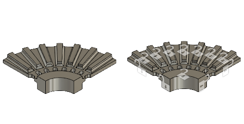
Brake rotor without constraints (left) and with applied constraints (right).
Prerequisites
- Activity 2 is complete.
Steps
Constrain the two faces on the YZ plane of the brake rotor, using the
 Select Face Priority selection mode.Tip: When a load or constraint dialog is open, you do not have to hold the Ctrl key down to select multiple entities. The mouse behavior in this case is to toggle the selection state of any clicked entity (or any entity affected by a selection rectangle). Just click each face you want to select.
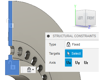
- Click
 (Simulation workspace > Setup tab > Select panel > Selection Priority > Select Face Priority) to activate the Select Face Priority command.
In the Select panel, a black checkmark on the command indicates which selection priority is active (Face or Body). - Select
 (Simulation workspace > Setup tab > Constraints panel > Structural Constraints) to open the Structural Constraints dialog.
 - Make sure the Type is set to Fixed.
- Click Uy and Uz to deactivate these axes. Only Ux is now active.
- Rotate the model and select the two faces on the YZ plane of the brake rotor.
- Click OK to accept the command and close the dialog.
- Click
Repeat steps b through f but this time, constrain only the Uy direction for the two faces on the XZ plane:
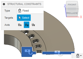
Window select the eight faces on the XY plane and constrain them in the Uz direction.
Tip: When using a selection rectangle, click and drag from left-to-right to select only items fully contained within the rectangle. Click and drag right-to-left to select all entities that the rectangle touches (cuts through) as well as any that are fully contained within the rectangle.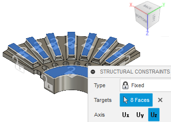 Note: Use the LEFT, RIGHT, TOP, or BOTTOM view, to select the XY plane faces in one operation (Z-constraint) with a single rectangle.
- Rotate the model as shown in the image, and select one of the eight faces.
- Select
 (Simulation workspace > Setup tab > Constraints panel > Structural Constraints) to open the Structural Constraints dialog.
 - Make sure the Type is set to Fixed.
- Click Ux and Uy to deactivate these axes. Only Uz is now active.
- Click BOTTOM on the ViewCube, then window select the top edge of the brake rotor, from left to right.
Note: The first face you selected is deselected in this operation, and needs to be selected again.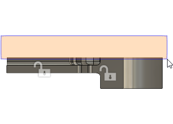
- Click the corner of the ViewCube to reorientate the model as shown in the image, then reselect the eighth face.
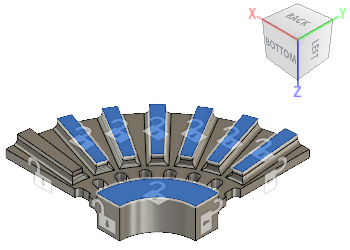
- Click OK to accept the command and close the Structural Constraints dialog.
Activity 3 summary
In this activity, you
- Changed the selection mode to Select Face Priority to make face selection easier
- Practiced using the different selection variations.
- Applied fixed structural constraints in each of the X-, Y-, and Z-directions, where the faces of the one-eighth model variant meet the faces of the other seven variants.