Activity 4: Apply loads
In this activity, you apply a combination of structural and thermal loads to the brake rotor. You
Apply a pressure to the hub bore face to represent the mechanical load caused by an interference (shrink fit) between the shaft and rotor.
Add an applied temperature to the same hub bore face. This face is in contact with a water-cooled shaft and, therefore, has a well-maintained temperature.
Apply a heat source to the pad contact face to represent the heat generated by friction during braking.
Apply a convection load to all faces that are exposed to ambient air, excluding the pad contact face.
This assumption is conservative, because it ignores the air-cooling that occurs on the portion of the friction face that is not covered by the brake pad.
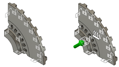
Brake rotor without loads (left) and with structural and thermal loads (right).
Prerequisites
- Activity 3 is complete.
Steps
Apply a structural load of 13.8 MPa to the hub bore face.
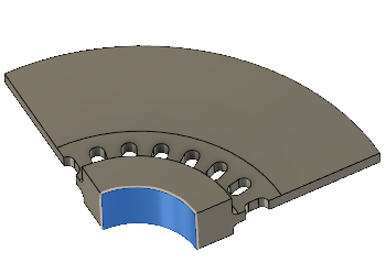
- Select
 (Simulation workspace > Setup tab > Loads panel > Structural Loads) to open the Structural Loads dialog.
 - In the Structural Loads dialog, set the Type to
 Pressure.
 - Select the face of the bore at the center of the rotor hub.
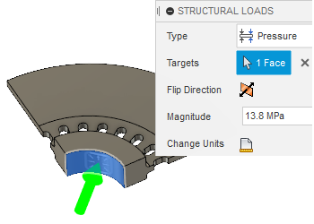
- Set the Magnitude to 13.8 MPa.
- Click OK to accept the command and close the dialog.
- Select
Add thermal load of 38 C to the same hub bore face.
- Select
 (Simulation workspace > Setup tab > Loads panel > Thermal Loads) to open the Thermal Loads dialog.
 - In the Thermal Loads dialog, set the Type to
 Applied Temperature.
 - Click the face of the hub bore at the center of the rotor, to select it as the face.
- Set the Temperature Value to 38 C.
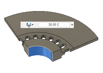
- Click OK to accept the command and close the Thermal Loads dialog.
- Select
Apply a heat source of 36500 W / (m^2 K) to the pad contact face, on a per-unit-area basis.
- Select
 (Simulation workspace > Setup tab > Loads panel > Thermal Loads) to open the Structural Loads dialog.
 - In the Thermal Loads dialog, set the Type to
 Heat Source.
 - Select the face of the rotor that is engaged by the brake pad.
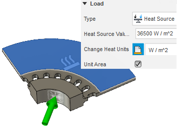
- In the Thermal Loads dialog, activate the Unit Area option. You are specifying the heat source on a per-unit-area basis, rather than the total heat input.
- Click
 Change Heat Units and select W / m^2 from the adjacent drop-down list.
 - Set the Heat Source Value to 36500 W / (m^2 K). This value represents the average heat input over time for multiple start/run/stop cycles.
- Click OK to accept the commands and close the dialog.
- Select
Apply a convection load to all the faces that are exposed to ambient air, excluding the pad contact face. Start by selecting all the faces of the brake rotor and choosing Convection from the Thermal Loads dialog. Then deselect the faces that are exempt.
- Click
 (Simulation workspace > Setup tab > Select panel > Selection Filters) and verify that the Select Through option is enabled. If not, click the checkbox to enable it.
 Note: This option must be enabled to select faces on the back side that are hidden from the view.
- Click
 (Simulation workspace > Setup tab > Loads panel > Thermal Loads) to open the Thermal Loads dialog.
 - In the Thermal Loads dialog, set the Type to
 Convection.
 - Click and drag the mouse to draw a selection window enclosing the entire rotor model. The Thermal Loads dialog should indicate that 93 Faces are selected.
Note: The hub bore face is automatically excluded from the selection set because it already has a temperature load on it.
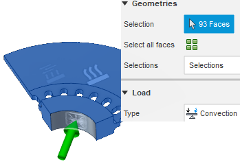
- Deselect faces that are not in contact with air. Remember, the symmetry planes represent a slice through solid portions of the full model:
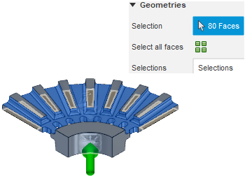
- The brake pad contact face (where the heat source was applied).
- Two faces on the XZ symmetry plane.
- Two faces on the YZ symmetry plane.
- Eight faces on the XY symmetry plane.
The Thermal Loads dialog should now indicate that 80 Faces are selected.
- Click
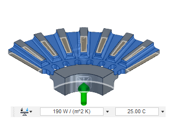
Apply a 190 W/(m^2 K) convection to the remaining 80 faces, at an ambient temperature of 25 C.
- In the Thermal Loads dialog, set the Convection Value to 190 W/(m^2 K).
This value takes the spinning of the rotor into account, which increases the speed of air flowing over and through the rotor. The value is significantly greater than what would be reasonable for natural convection driven by buoyancy alone.
- Change the Temperature Value to 25 C.
- Click OK to apply the commands and close the dialog.
- Click the
 Home view to restore the default isometric view of the model.
- In the Thermal Loads dialog, set the Convection Value to 190 W/(m^2 K).
Activity 4 summary
In this activity, you
- Applied a pressure to the hub bore face to represent the mechanical load caused by an interference (shrink fit) between the shaft and rotor.
- Added an applied temperature to the same hub bore face, which is in contact with a water-cooled shaft.
- Applied a heat source to the pad contact face to represent the heat generated by friction during braking.
- Applied a convection load to all faces that are exposed to ambient air, excluding the pad contact face.