Activity 2: Simplify the model to create an eighth-symmetry variant
In this activity, you use the Simplify environment to create an eighth-symmetry variant of the full disk brake rotor model. Changes made on a simulation model do not affect the production model, and are specifically for simulation purposes.
To create an eighth-symmetry simulation model from the full model, you
Split the original body three times, once using each of the three global planes
Remove seven of the eight derived bodies, leaving only one-eighth of the original body.
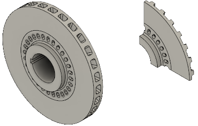
Full disk brake rotor model (left) and the eighth-symmetry variant model (right).
Prerequisites
- Activity 1 is complete.
Steps
Split the body in half using the XY plane as the splitting tool.
- Click
 (Simulation workspace > Setup tab > Simplify panel > Simplify) to open the Simplify environment.
 - Click
 (Simulation workspace > Simplify Solid tab > Modify panel > Split > Split Body) to open the Split Body dialog.
 - Click the brake rotor to select it as the Body to Split.
- In the Split Body dialog, click
 Select to activate the Splitting Tool selector.
 - In the Browser, expand
 Origin.
 - Click
 XY to select the XY plane as the splitting tool.
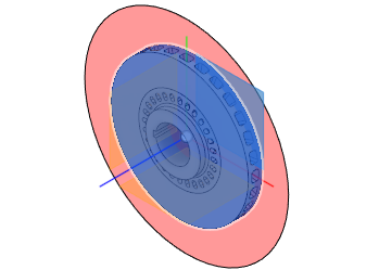
- Click OK to accept the command and close the Split Body dialog.
- Click
Split the model again, using the XZ plane as the splitting tool, to create four bodies.
- Right-click in the canvas and choose
 Repeat Split Body from the top of the marking menu.
 - Click and drag the mouse from right-to-left to draw a selection window that intersects the two bodies. When dragging the selection rectangle in this direction, you do not have to fully enclose the bodies to select them.
- In the Split Body dialog, click
 Select to activate the Splitting Tool selector.
 - Click
 XZ to select the XZ plane as the splitting tool.
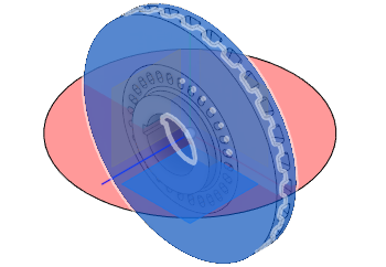
- Click OK to accept the command and close the Split Body dialog.
- Right-click in the canvas and choose
Split the model again, using the YZ plane as the splitting tool, to create eight bodies.
- Right-click in the canvas and choose
 Repeat Split Body from the top of the marking menu.
 - Click and drag the mouse from right-to-left to draw a selection window that intersects the four bodies.
- In the Split Body dialog, click
 Select to activate the Splitting Tool selector.
 - Click
 YZ to select the YZ plane as the splitting tool.
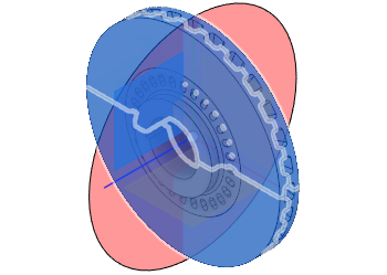
- Click OK to accept the command and close the Split Body dialog.
- Right-click in the canvas and choose
Remove seven of the eight bodies.
- If you have changed the model viewpoint since opening the model, click
 Home view above the ViewCube, to restore the default isometric view.
 - Click
 (Simulation workspace > Simplify Solid tab > Select panel > Selection Priority > Select Body Priority).
 - Click the segment of the rotor that is in the +X, +Y, +Z global quadrant.
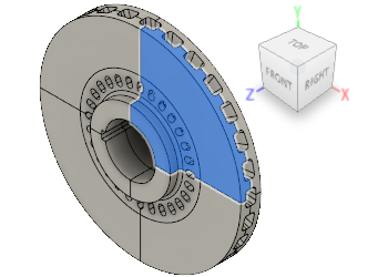
- Right-click in the canvas and choose
 Invert Selection from the context menu. The previously selected segment is deselected and the other seven segments are selected.
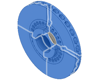
- Right-click in the canvas and select
 Remove from the context menu. Only the one rotor segment in the +X, +Y, +Z global quadrant remains.
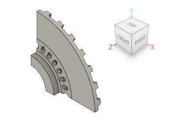
- Click
 (Simulation workspace > Simplify Solid tab > Finish Simplify panel > Finish Simplify) to return to the Simulation workspace.
- If you have changed the model viewpoint since opening the model, click
Activity 2 summary
In this activity, you
- Split the original body three times, once using each of the three global planes
- Removed seven of the eight derived bodies, leaving only one-eighth of the original body.