Activity 4: Create a new simulation model and thermal study
The size of the fins needs to be increased to reduce the temperature at the outer edge of the fins down below 70 C. Since you are experimenting with different designs, you don't want to change the production model just yet. Changes you make on a simulation model do not affect the production model.
In this activity, you
Create a new simulation model
Remove model components that have no influence on the simulation
Increase the width of the fins by 80 mm on each side
Increase the length of the fins by 65 mm on each end
Create a new thermal study and set the mesh size to 10 mm
Change the model material to aluminum.
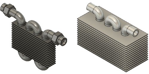
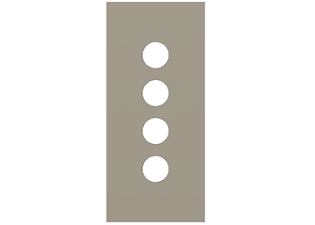
New simulation model (left). Simulation model simplified, with extended fins (right).
Prerequisites
- Activity 3 is complete.
Steps
Create a New Simulation Model.
- Click
 (Simulation workspace > Setup tab > Simplify panel > Simplify), to access the Simplify environment.
 - Click
 (Simulation workspace > Simplify Solid tab > Create panel > New Simulation Model), to create a new simulation model.
 Simulation Model 2 appears in the Browser, active and expanded.
- Click
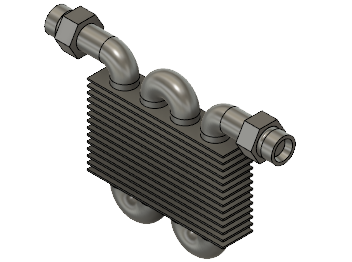
Remove the fittings and the water volume components, to reduce analysis time and provide a valid comparison with model 1.
- In the Browser, expand
 Model Components.
 - Right-click the
 Water:1 component, and select
  Remove.Note: Remove deletes the part from the simulation model. The only way to bring back a part is to delete the Remove command from the Timeline or create a new simulation model.
 - Repeat step b to remove the
 Fittings:1 component.
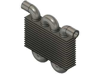
 - Click Home View next to the ViewCube to return the model to its original size and orientation.
- In the Browser, expand
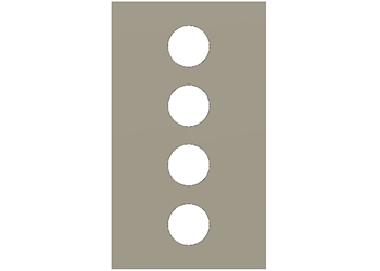
Increase the width of the fins by 80 mm on each side.
- In the Browser click
 next to Pipe to hide it.
 - Click the TOP face of the ViewCube to adjust the orientation of the fins.
- Click
 (Simulation workspace > Simplify Solid tab > Create panel > Extrude) to open the Extrude dialog.
 - Left-click to the left and above the model and drag a window selection over the edges on the left side of the model.Note: It is important to pull the selection window to the right to select only those profiles that are entirely contained within the selection window.
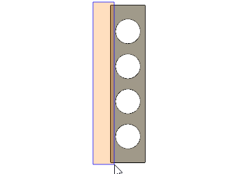
- In the Extrude dialog, make the Distance 80 mm.
- Confirm that 14 profiles are selected, and the Operation is Join, then click OK to accept the commands and close the dialog.
- Repeat steps c. to f. to extend the other side of the fins by 80 mm.
- In the Browser click
Increase the length of the fins by 65 mm on each end.
- Click
 (Simulation workspace > Simplify Solid tab > Create panel > Extrude) to open the Extrude dialog.
 - Left-click to the left and above the model and drag a window selection to the right over the top end of the model.
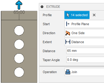
- In the Extrude dialog, make the Distance 65 mm.
- Confirm that 14 profiles are selected, and the Operation is Join, then click OK to accept the commands and close the dialog.
- Repeat steps a. to d. to extend the bottom end of the fins by 65 mm.
- Click
 (Simulation workspace > Simplify Solid tab > Finish Simplify panel > Finish Simplify) to return to the Setup tab.Note: The New Study dialog opens automatically.
- Click
Create a new Thermal analysis study, and set the mesh size to 10 mm.
- In the New Studies dialog box, select
 Thermal.
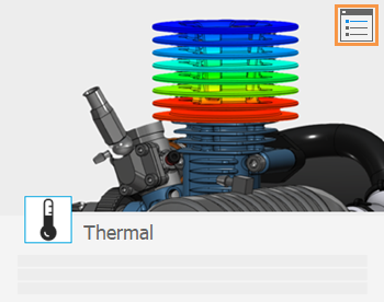
 - In the upper right corner of the large thumbnail image, click the
 Settings icon to access the Settings dialog.
- Select Mesh from the left frame of the dialog to display the mesh settings.
- Click Absolute Size and type 10 mm in the input field.Note: By using the Absolute mesh size you ensure that your results are based on a comparable mesh size.
- Click Back to apply the changes.
- In the New Study dialog, click Create Study to create the study and close the dialog.
- In the New Studies dialog box, select
Change the material for the Radiator model to Aluminum.
- Click
 (Simulation workspace > Setup tab > Materials panel > Study Materials) to open the Study Materials dialog.
 - In the Study Materials dialog, click Select All in the bottom-left corner to select all components.
- Change the Study Materials for one of the drop-down menus to Aluminum.
- Click OK to close the Study Materials dialog.
- In the Browser, expand
 Model Components.
 - Click
 next to Pipe to make it visible.
 - Click
 Home view above the ViewCube to return the model to its original size and orientation.
- Click
Activity 4 summary
In this activity, you
- Created a new simulation model
- Removed model components that have no influence on the simulation
- Increased the width of the fins by 80 mm on each side
- Increased the length of the fins by 65 mm on each end
- Created a new thermal study and set the mesh size to 10 mm
- Changed the model material to aluminum.