Activity 4: Apply loads, define contacts, and refine the mesh
In this activity you prevent stress exaggerations on the part that might result from instantaneously jumping from rest to 3000 mm/s. You then make adjustments to the study set up, some to reduce the analysis time, and others to improve the accuracy of the results. To complete the study set up, you
- Apply an initial linear velocity to the movable part, to specify that the part is already in motion at the start of the event
- Define the global contacts settings to disable self-contact
- Refine the mesh where the two bodies connect.
Prerequisites
- Activity 3 is complete.
Steps
Apply an Initial Linear Velocity of -3000 mm/s to the moving part in the Z direction.
This action prevents the shock of instantaneously accelerating the moving part at the beginning of the event. Essentially, we're saying that the part is already in motion at the beginning of the event.
Click
 (Simulation workspace > Setup tab > Loads panel > Initial Linear Velocity) to open the Initial Linear Velocity dialog.
Click the moving part to select it as the Body.
Ensure that the Direction Type is set to
 Vectors (x, y, z) .
Type -3000 mm/s in the Z Velocity Component field.
Note: Ensure the units are set appropriately, and change them if they are not.Click OK to accept the settings and close the dialog.
Automatically detect body-to-body contact pairs and suppress self-contact.
In event simulation studies contact pairs are defined between bodies, not between individual points, edges, or faces, and are detected automatically. Self-contact, where a part can deform and come into contact with a different area of itself, is supported. For this exercise, since we do not expect self-contact we can disable it to shorten the solution time.
Click
 (Simulation workspace > Setup tab > Contacts panel > Global Contacts), to open the Global Contacts dialog.
Confirm that Global Separation Contact is enabled and Proximity Bonded Contact is disabled.
Note: Separation contact interaction occurs wherever the two parts touch during the simulation. The parts can slide along each other and separate from each other freely, but are not permitted to penetrate each other.Expand Advanced Settings.
Deactivate Allow Self Contact.
Click Generate to create the contact pairs and close the dialog.
Change the mesh length to 1 mm on both parts, where the locking fingers of the moving part contact the stationary part as the two connect, as follows:
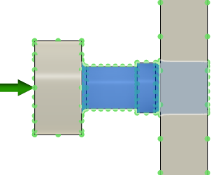
(i) On the locking fingers of the stationary part (all faces, including the fillets where it meets the main portion of the body. You want a finer mesh here to capture more accurate bending stresses. The fillets at the base of the fingers are stress concentration and critical stress regions. You also want to produce a smooth mesh in the contact region, that conforms more accurately to the cylindrical shape of the CAD model.
(ii) In the middle hole and its chamfer on the stationary part, to produce a smooth mesh in the contact region of this part.
Using the ViewCube, change the model viewpoint to show the Bottom view of the model, as shown in the image below.
Click
 (Simulation workspace > Setup tab > Select panel > Selection Filters) and ensure that Select Through is activated.
This is necessary so that hidden faces are included when we select the areas to refine the mesh.
Click
 (Simulation workspace > Setup tab > Manage panel > Local Mesh Control) .
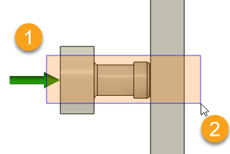
Click and drag the mouse from left to right to enclose the area indicated in the following image:

The Edit Local Mesh Control dialog should indicate that 18 Face/Edges are selected.
Note: When you click and drag the mouse from left to right, only the entities that are fully enclosed within the rectangle are selected. If you click and drag the mouse from right to left, everything the rectangle crosses through is selected, which is not what we want.Type 1 mm in the Length field to set the local mesh size.
Click OK to accept the settings and close the dialog.
Tip: In the Browser, expand the Local Mesh Controls node, hover over Local Mesh:1 and click Edit to see the mesh refinement along the surface of the entire part. You can see that the edge length is now smaller where the two parts connect.
Activity 4 summary
In this activity, you
- Applied an initial linear velocity to the movable part, to specify that the part is already in motion at the start of the event
- Defined the global contacts settings to disable self-contact, to decrease the solve time
- Decreased the mesh length where the two bodies make contact, to improve the solve accuracy.