Learn how to draw and copy beams.
- Continue working in your project, or open the project
Tutorial_Alpha_Supports.rstructure.
Note: To open the project, click Explore Tutorials from the Welcome Screen or navigate to the Tutorials folder C:\Users\Public\Public Documents\Autodesk React Structures Tech Preview\Tutorials.
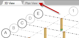
- Click the
Plan View tab to switch to a plan view of the model.
- Click
Model
 Structural Elements
 Beam.
Beam.
The Mode and Beam Properties panels display in the ribbon.
- In the Mode panel, select
 Horizontal to draw beams in the XY plane.
- In the Beam Properties panel:
- Select the Concrete material from the drop-down menu.
- Select the B 8x16 section from the drop-down menu.
- In the drawing area, click the point of axis intersection A1 (x:0.00, y:15.00) to specify the first point of the beam.
- In the drawing area, click the point of axis intersection
C1
(dx:0.00, dy:30.00) to specify the next point of the beam.
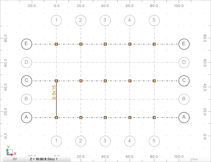
The first beam displays in the drawing area.
-
In the dynamic input tooltip, specify the first point of the second beam:
- Enter the 0.00 absolute coordinate in the x: input box, press Tab,
- Enter the 45.00 absolute coordinate in the y: input box, press Enter.
The first point of the second beam displays in the drawing area.
Note: For more information about the dynamic input tooltip, see About Using Dynamic Input Tooltips. - In the dynamic input tooltip, specify the next point of the second beam:
- Enter the 0.00 relative coordinate in the dx: input box, press Tab,
- Enter the 30.00 relative coordinate in the dy: input box, press Enter.
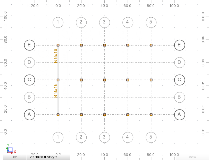
The second beam displays in the drawing area.
- Click
Model

 Select.
- Press and hold
Ctrl, and then click the first and the second beam in the drawing area.
The beams highlight as shown below.

- Click
Model
 Modify
 Copy.
Copy.
The Copy panel displays in the ribbon.
- In the Copy panel, enter 4 in the Repeat box.
- In the drawing area, click the point of axis intersection A1 (x:0.00, y:15.00) to specify the first point of the translation vector.
- In the drawing area, click the point of axis intersection
A2
(dx:20.00, dy:0.00) to specify the endpoint of the translation vector.
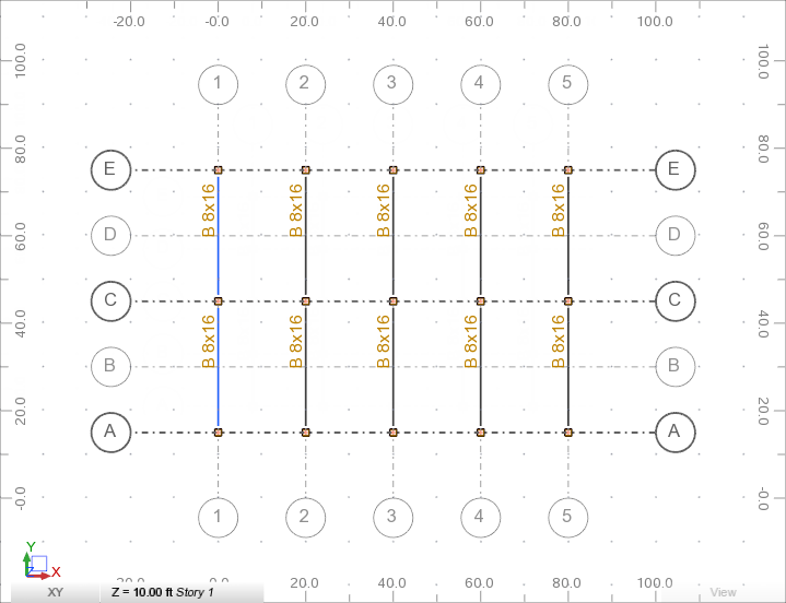
The beams display in the drawing area as shown below.
- Press Esc twice to exit the copy tool.
- In the drawing area, click anywhere to deselect the beams.
- Click
Model
 Structural Elements
 Beam.
Beam.
The Mode and Beam Properties panels display in the ribbon.
- In the Mode panel, select
 Chain.
The Chain feature places the beams continuously as you draw them.
- In the Beam Properties panel, select
B 10x12 from the Section drop-down menu.
Note: If the B 10x12 section doesn't appear on the list, see Add Sections.
- In the drawing area, click the point of axis intersection A1 (x:0.00, y:15.00) to specify the first point of the beam.
- In the drawing area, click the point of axis intersection
A2
(dx:20.00, dy:0.00) to specify the next point of the beam.
The last endpoint is the start point for the next beam.
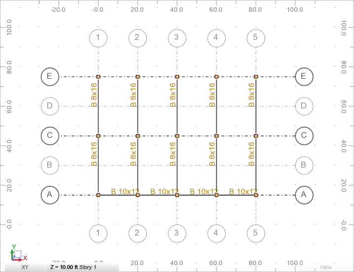
- In the drawing area, click the following grid intersections or use the dynamic input tooltip to add additional beams in the axis A:
- A3 (dx:20.00, dy:0.00)
- A4 (dx:20.00, dy:0.00)
- A5 (dx:20.00, dy:0.00)
The beams display in the drawing area as shown below.
- Press Esc twice to exit the beam tool.
- Press and hold
Ctrl, and in the drawing area click beams defined in the axis A.
The beams highlight in blue.
- Click
Model
 Modify
 Copy.
Copy.
The Copy panel displays in the ribbon.
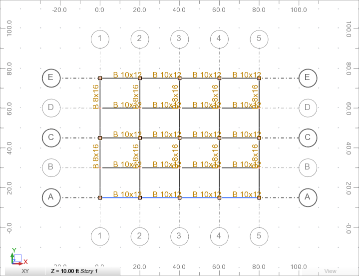
- In the Copy panel, enter 4 in the Repeat box.
- In the drawing area, click the point of axis intersection A1 (x:0.00, y:15.00) to specify the first point of the translation vector.
- In the drawing area, click the point of axis intersection
B1
(dx:0.00, dy:15.00) to specify the endpoint of the translation vector.
The beams display in the drawing area as shown below.
- Press Esc twice to exit the copy tool.
- In the drawing area, click anywhere to deselect the beams.
- Click the
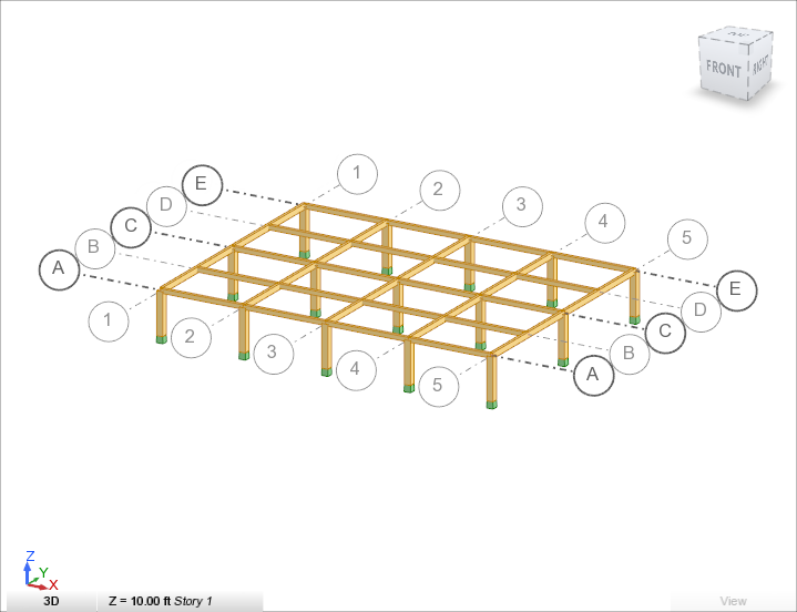
3D View tab to switch to a 3D view of the model.
- Save the project as Tutorial_Alpha_Beams.rstructure.