Import composite files so you can create manufacturing analyses and strategies. The workflow for import depends on whether you are importing standard composites, or composites created using Fibersim software.
Import Standard Composites
Use the Open Composites
 or Insert Composites
 features to import composite data from a third-party CAD system into your host application (that is, Autodesk Inventor). First you open an XML file containing the structure for your project, then you add the STL files that contain the corresponding workpiece surfaces. Autodesk recommends that the STL file names correspond to their surface names in the XML file. If you make changes to the referenced STL files using CAD software, the changes will be reflected in
TruPlan.
features to import composite data from a third-party CAD system into your host application (that is, Autodesk Inventor). First you open an XML file containing the structure for your project, then you add the STL files that contain the corresponding workpiece surfaces. Autodesk recommends that the STL file names correspond to their surface names in the XML file. If you make changes to the referenced STL files using CAD software, the changes will be reflected in
TruPlan.
- Click
Open Composites or
Insert Composites on the
TruPlan ribbon.
(The name of the button depends on whether you already have a file open.)
- Browse to the XML file you want and click
Open.
The Import Options dialog box opens.
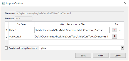
- In the Import Composites dialog box, select the STL files to import.
The Workpiece Source File boxes are editable; you can enter direct paths to your files if you want.
- To calculate ply offset values for laser projection output, select
Create Surface Update Every.
Offset values are the thicknesses that are calculated as plies are laid on top of one another. With large projects, creating many offset values can create a lot of data and increase file size. If you want to avoid this, some alternatives are to:
- Next to Create Surface Update Every, enter a ply interval value for offset creation that is distinctly higher than 1; for example 5. This will still give you a close thickness approximation throughout the part without greatly increasing file size.
- Leave Create Surface Update Every deselected and, after import, set up offset calculation using the Strategy dialog box. This type of calculation does not increase file size, but could start to impact performance if used extensively.
You probably do not need to calculate surface offsets on import if you are just trying to evaluate the general shape of a part. You can always calculate offsets later on by right-clicking a ply and selecting Include Surface Offset.
Tip: See Working with Thickness Calculation.
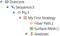
After import, the structure of the XML is shown in the TruPlan browser on the left side of the application window, including:
- Root node
- Ply geometry
- Materials
- Rosettes
- Layups
- Sequences
When you save the project, the name of the XML file is used as the application default part file name; for example, in Inventor, Lowerupper.xml will result in the default file name Lowerupper.ipt when you save.
Change Referenced STL files
After import, you can decide to reference a different STL file.
- In the TruPlan browser, navigate to the surface whose file reference you want to change.
- Do one of the following:
- Double-click the surface name, or;
- Select the surface name and click
Reference Surface
 on the
TruPlan ribbon.
on the
TruPlan ribbon.
The Reference Surface dialog box opens.
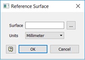
- Click Browse
 and select a file to reference.
Alternatively, enter the direct path to the file in the Surface box.
- Select the appropriate value from the
Units box.
This must correspond the value used when creating the STL file, otherwise the scale will be wrong in TruPlan.
- Click OK.
Import Fibersim Composites
Fibersim composites files contain information that TruPlan is able to read and use to create strategies during import. This includes surface geometry, seed points and curves, rosette locations, and strategy information such as propagation type and other parameters. Start the import process as you would with standard composites; that is, click Open Composites or Insert Composites, select a file, and set a surface update preference. Next, follow these steps to create strategies during import. TruPlan automatically detects that this is a Fibersim file, shows the appropriate strategy options, and loads strategies into the Import Options dialog box.
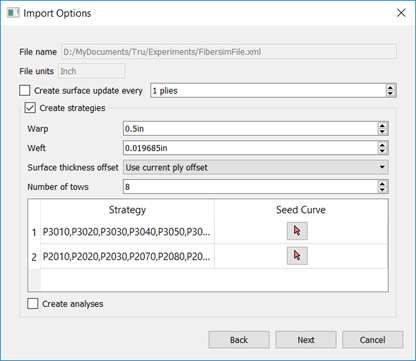
- Set
Warp and
Weft for the strategies.
These are the length and width, respectively, of the cells in the analysis mesh.
- Set
Surface Thickness Offset.
This determines how to use surface offsets when creating a fiber path and mesh for each strategy.
- Use Existing: Use the most recently stored ply offset that precedes the strategy. This can provide a reasonably accurate representation of thickness without requiring a lot of processing power.
- Use Current Ply: Calculate the offset value within the strategy itself. This provides the most accurate representation of thickness but can use a lot of processing power.
-
Disabled: Do not take offsets into account.
Tip: See Working with Thickness Calculation.
- Number of Tows: The number of tows you want per band of material.
- To set a seed curve for strategies in a row, click the appropriate selection arrow
 and select a curve projection in the
TruPlan browser.
and select a curve projection in the
TruPlan browser.
- Select
Create Analyses to automatically create all available analyses types for the strategy.
Analyses provide assessments of the fiber path and surface mesh grids of a strategy to find irregularities or distortions. There are several kinds available in TruPlan. If you do not select this option, you can create different types of analyses later.
- Click
Next.
The Strategy Table dialog box opens.
- Make any changes you want to the list of strategies and click Finish.
Once import is finished, expand layup and sequence nodes to see strategies and analyses (if they were created).