
If you are working with motion-capture data and would like to bring point-cloud data into 3ds Max and then map the motion onto a CATRig, this topic can help. Rather than a tutorial, this is an example of how to solve this problem.
This is an exercise in configuring constraints to solve a complex integrated problem. Constraints are directional. In other words, if A is constrained to B, then B cannot reference A. The inability of constraints to support circular relationships means that we are forced to take a layered approach to the problem.
The desired result is a set of bones with correctly animated joint positions and rotations. One simple way to solve this problem is to break the problem into two simpler problems, positions and rotations, and solve them separately. The postion of a bone does not depend on any other bones in the skeleton, nor does it depend on the rotation of any other bone.
CAT simplifies the solution to this problem.
- The Capture Animation tool makes it easy to map the CATRig to the bones rig. Each bone can contain offsets that lets you interactively adjust the pose of the CATRig while the motion is being mapped onto the rig.
- The procedural spine makes it unnecessary to specify each bone in the spine. Given position and orientation data for the pelvis, ribcage, and head, CAT's procedural spine can interpolate the vertebrae accurately.
- With CAT's IK system, you can constrain CATRig bones to the imported rig and let the software handle the IK solution. The retargeting feature means that even if the legs of the character go very straight and the CATRig has legs that are longer or shorter that the original leg, the pose of the CATRig will be ajusted to fit the data.
Example Scene
The following illustrations depict the process of mapping a CATRig to imported point-cloud data.
Point Cloud
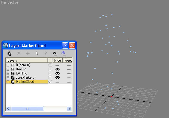
The original motion-capture data cloud
Joint Positions
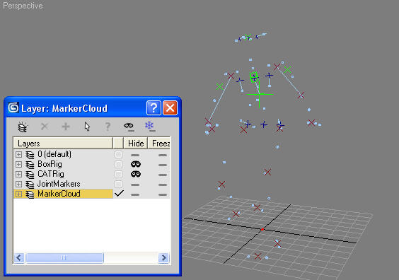
The first layer is for generating joint positions in the cloud using Point constraints. The joint positions are simply weighted Position constraints, and therefore relatively easy to set up. The red crosses in the scene file represent basic joint position helpers.
A group of three Point helpers is used to define the pelvis orientation based on surrounding markers. An identical setup is used to drive the orientation of the ribcage and head. These are the blue points in the illustration.
Box Rig
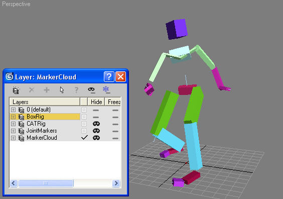
The second layer is the BoxRig, which defines the joint angles. Boxes are constrained to the joint positions and LookAt controllers define rotations. Note that the exact position of many of the bones is not important. For example, the knee joints move relative to the hip bone, but when this data is mapped onto the CATRig, the latter’s IK system effectively cleans up the motion and locks the joint locations.
CATRig
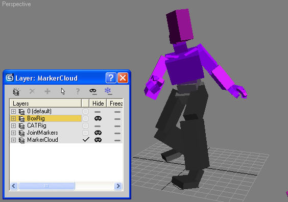
The CATRig has been mapped onto the BoxRig using the Capture Animation tool.