
Learn how the check results and errors of generated user sections are displayed in the Data Panel and the ways you can mark the displayed information in the model.
- When all user sections or a selection of user sections are generated from an Advance Steel file, the Data Panel will open, listing the results in the dedicated User Section Generation tab (
 ).
).
- The Data Panel list only shows the results for the user sections in the current active model. If sections were generated in multiple models that are currently open in Advance Steel, you need to activate each of the models to see the results specific to a certain model.
- In an active model where no sections were generated, there will be no results to show, so the User Section Generation tab will not appear at all in the Data Panel.
- If different types of actions that show results in the Data Panel were performed in a model, such as numbering, user section generation, or clash check, each corresponding result type will be displayed in its dedicated tab in the Data Panel.
- In a specific model, the results are available in the Data Panel even after closing and reopening the Data Panel.
- If user sections are generated again in a model, the Data Panel tab will only show the results for the user sections generated in the latest iteration, the results of the previous iterations will be removed.
- Double-click on an entry in the Data Panel to zoom in on the frame of that specific section definition from the model.
- If the section definition is correct and the section is generated, the "Section successfully created" message will be displayed in the Status column of the Data Panel, also referencing the section type and section name.
- If a specific section definition has errors, they will be reported in the Status column of the Data Panel, also referencing the section type and section name.
- If the section definition has multiple errors that prevent it from being generated, only the first detected error will be displayed in the Data Panel.
- In some cases, a user section will show an error message, even if it is successfully generated. This usually happens when the error is pointing to the simple or exact inner contour, while the outer contour is correctly generated. In such cases, there will be two entries in the Data Panel, both pointing to the respective section.
Marking User Section Errors
To identify and fix the errors in the Data Panel list:
- Double-click on an error in the Data Panel to zoom in on the frame of a specific section definition or on the specific area of that definition where the problem is located. A red circle marking is also placed around the section frame or around the specific area, depending on the type of error.
- Single-click on an error in the Data Panel to only display the red marking around the frame or area of a specific section.
OR
Search for Marked User Sections
To search for marked sections:
- In the Data Panel
 (User Section Generation) tab, on the bottom right side of the panel, click
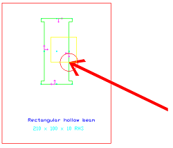
 (Search marked object). This command will display an arrow pointing to the center of the red marking in the model.
To remove the arrow and marking from the drawing space:
- In the Data Panel
(User Section Generation) tab, on the bottom right side of the panel, click
 (Clear marked objects).
| ERROR TYPE IN DATA PANEL | MARKING |
|---|---|
| Inner contour not closed | A red circle is created around one of the open-end points of the polyline defining the inner contour. |
| Inner contours overlap | circle around one of the points where the inner contours intersect |
| Inner contour overlaps outer contour | A red circle around one of the points where the inner and outer contours intersect. |
| Inner contour is self-crossing | A red circle around one of the points where the inner contour is self- intersecting. |
| Outer contour is self -crossing | A red circle around one of the points where the outer contour is self- intersecting. |
| Simple outer contour not closed | A red circle around one of the open-end points of the polyline defining the simple outer contour. |
| Exact outer contour not closed | A red circle around one of the open-end points of the polyline defining the exact outer contour. |
| In some other error cases, the red circle marking is created around the entire contour polylines from the definition that cause the error: | |
| Inner contour inside other inner contour | A red circle around the smaller inner contour. |
| Inner contour outside outer contour | A red circle around the inner contour. |
| Too many outer contours defined | A red circle around one of the outer contours. |
| No outer contour defined | A red circle is created around the red frame of the section definition. |
| No section name defined on layer | |
| No section type name defined on layer | |
| Too many section type names defined on layer | |
| Section has "x" vertices, only "y" are allowed | |
| Warning: more than one upper left axis system defined, ignoring second - The section has more than one reference axis defined for the same position (e.g. Upper left). | A red circle around one of the duplicated reference axes. |
| Section class name contains invalid character - The section type name contains an unsupported special character. | A red circle around the text. |