
When you draw a schematic line, you can select a style for the line on the Properties palette. The style determines the annotation properties for the line, such as the symbols used to represent start points, endpoints, and connections.
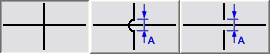
The style of a schematic line also determines how crossing lines are displayed. You can display crossing lines as is, or with an overlap or a break of a specific width.
If you select the overlap style or break style, you must also specify a corresponding priority value. In a drawing, if 2 crossing lines have the same priority value in their corresponding styles, the line with the lower Z-axis value will display the overlap or break. If the priority values are different, the priority values determine this. Refer to the following table for more information.
| If the crossing style of the 2 lines is... | And if the priority values of the 2 lines are... | Then... |
|---|---|---|
| overlap | the same | the line drawn second displays the overlap. |
| break | the same | the line drawn first displays the break. |
| mixed (one is overlap, and the other is break) | the same | the line drawn second determines the crossing style to use. If the style is overlap, the line drawn second displays the overlap. If the style is break, the line drawn first displays the break. |