
You can draw a schematic diagram in orthographic (plan) mode. Orthographic mode enables you to draw the diagram in a 2D plan view.
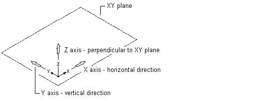
When you draw in orthographic mode, you add schematic lines and symbols in the world coordinate system (WCS). In the WCS, the X axis is horizontal, the Y axis is vertical, and the Z axis is perpendicular to the XY plane.
Orthographic drawing parameters
As you add or move lines or symbols, you can use several tools to restrict cursor movement:
- Use the compass to guide the placement of lines or symbols.
- Use the AutoCAD® Ortho mode to restrict the cursor to the horizontal or vertical axes. The orthogonal alignment depends on the current snap angle, or grid and snap settings.
- Use the grid to help you to align symbols and visualize the distances between them.
- Use snaps for specifying precise points for placement of symbols or lines.
You can turn these tools on or off at any time during drawing and editing.