
- Open the drawing that contains the corridor or corridor reference.
- Select the corridor in the drawing.
- Click
Corridor tab
 Corridor Tools panel
Extract Corridor Solids
Find.
Corridor Tools panel
Extract Corridor Solids
Find.
The following prompt is displayed:
Select corridor regions to export as solids or [Station range within Polygon All regions]: - Do one of the following:
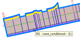
- Select the corridor regions: When you move your cursor over the corridor, the regions are highlighted and the region name is displayed in a tooltip.
 Note: If another command line option is currently active, enter R for by Regions to activate this option.After you complete your selection set, press Enter.
 - Enter
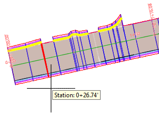
S to specify a station range, select the region from which to define the station range, and then specify the station range by selecting in the drawing or by entering values at the command line.
- Enter
P to select within an existing closed polygon.
After you complete your selection set, press Enter.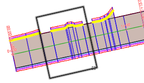
- Enter A to select all corridor regions.
The Extract Corridor Feature Lines wizard is displayed.
- Select the corridor regions: When you move your cursor over the corridor, the regions are highlighted and the region name is displayed in a tooltip.
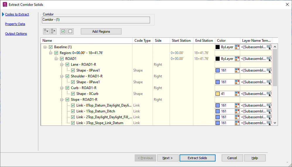
- In the
Create Solids From Corridor wizard, on the
Codes To Extract page, set the following:
- Make any
color settings for assemblies, shapes, or links. Click the
 icon to open the Select Color dialog box for a selected assembly, shape, or link. Assign a color from the palette to the shapes and links you want extracted.
Tip: After setting a color for one shape or link, open the context menu and click Apply Settings to All Sibling Nodes. This lets you quickly synchronize multiple shape and link settings.
icon to open the Select Color dialog box for a selected assembly, shape, or link. Assign a color from the palette to the shapes and links you want extracted.
Tip: After setting a color for one shape or link, open the context menu and click Apply Settings to All Sibling Nodes. This lets you quickly synchronize multiple shape and link settings. - Specify the
Layer Naming Structure for assemblies, shapes, and links. Click
 to open the Name Template dialog box. From the Property Fields list, set the layer naming structure you want to use and click Insert.
Tip: To set an extended naming structure like <[Construction Region Name]> <[Subassembly Name]> <[Shape Codes]>, consecutively select each property from the list and click Insert after each selection.
to open the Name Template dialog box. From the Property Fields list, set the layer naming structure you want to use and click Insert.
Tip: To set an extended naming structure like <[Construction Region Name]> <[Subassembly Name]> <[Shape Codes]>, consecutively select each property from the list and click Insert after each selection.
- Make any
color settings for assemblies, shapes, or links. Click the
-
On the
Property Data page, specify which property set definitions to associate with the extracted solids. Click each property set definition and then select the Visible check box for each property that you want to be able to view for the extracted solids.
Tip: You can add definitions to the Corridor Property Data - User Defined set by right-clicking in the grid and selecting Add.Note: The Visible check box controls whether the property will be visible on the Extended Data tab in the AutoCAD Properties Palette or in other applications such as Autodesk® Navisworks®.
- On the
Output Options page, set the following:
- Specify the object type you want to extract such as
Bodies, Solids, or Swept Solids.
Note: Links are always exported as bodies rather than solids (regardless of the object type you choose to create).Note: When choosing to extract AutoCAD bodies from a corridor, shapes and links are used to generate a model that matches the way the corridor is constructed. While AutoCAD bodies are visually similar to AutoCAD solids, there are some limitations to extracting bodies. For example, functions like calculating mass properties do not work on AutoCAD bodies.
- Select one of the Output Destination options.
- Specify whether the solids will remain dynamic to the corridor.
- Specify the object type you want to extract such as
Bodies, Solids, or Swept Solids.
- Click Extract Solids.