
Use the Rehab Corridor Editor to view and modify rehab corridor sections and to visually inspect how rehab subassemblies are applied at various stations within rehab corridor regions.
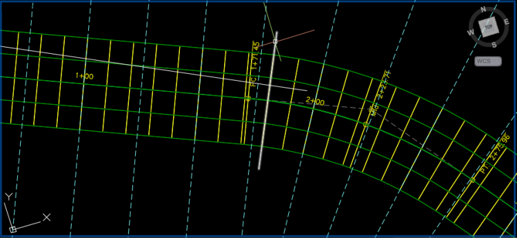
When you select a rehab region within a rehab corridor, three default viewports will be displayed, allowing you to view the corridor cross section for the station (cross section view), the vertical profile for the section (profile view), and the location of the corridor cross section along the rehab corridor's alignment (plan view).
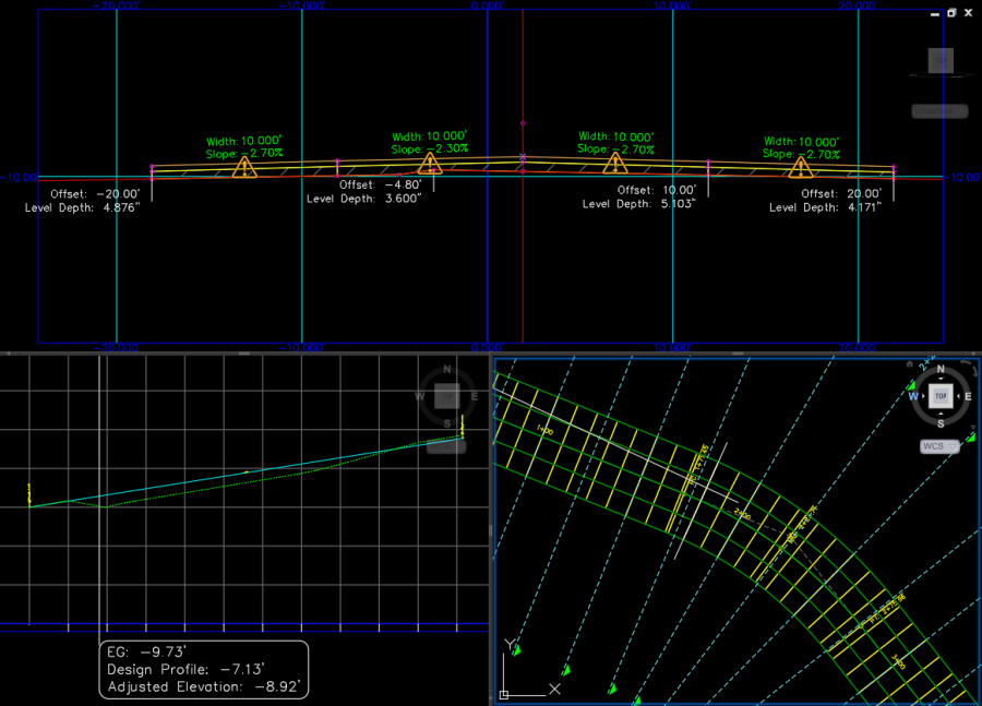
Cross Section View
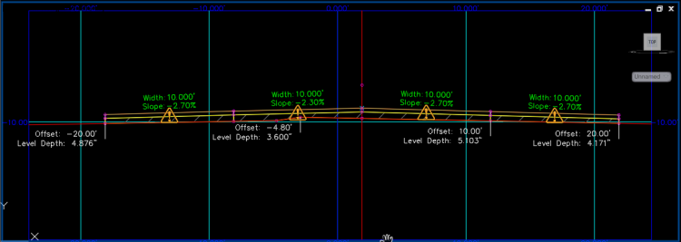
- Width: The width of the lane at the selected station.
- Slope: The accepted cross slope (%) for the selected station.
- Offset: The distance of the outside edge of the lane from the road centerline.
- Mill/Level Depth: The depth of the milling and/or leveling layer at the selected station.
- Violations: Hover your cursor over a violation icon to view violations.
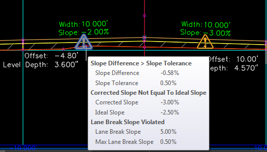 Note: There are four possible violation types:
- Slope
If the absolute value of Slope Difference is greater than the absolute value of Slope Tolerance, a violation is displayed.
If Corrected Cross Slope is not equal to Ideal Cross Slope, a violation is displayed.
- Relative Gradient
If the change in corrected slope between two stations relative to the distance in length between the stations is greater than the maximum relative gradient, a violation is displayed.
- Lane Break
If the difference in accepted slope between two lanes is greater than the maximum lane break slope, a violation is displayed.
- Slope
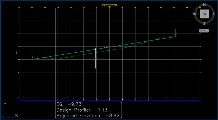
- Existing Ground (EG)
Elevation of the existing ground profile for the selected station.
- Design Profile
Elevation of the design profile for the selected station. The design profile elevation for a rehab corridor region is defined by the vertical baseline that was assigned to the rehab corridor in Corridor Properties during rehab corridor creation.
- Adjusted Elevation:
For an undivided rehab corridor section, Adjusted Elevation is equal to the crown point elevation for the selected station.
For a divided rehab corridor section, the Adjusted Elevation is equal to the elevation of the highest elevation crown point of any other crowned subassembly in the assembly. If no crown point exists in the assembly, Adjusted Elevation is set to equal to the Design Profile elevation. If the assembly has a median on the centerline that separates the right and left lanes, the adjusted elevation is equal to the design profile elevation. If there is not a subassembly attached to the baseline, the adjusted elevation is equal to the design profile elevation.