
When programming directly on a solid model of a part, it is important to understand the following concepts:
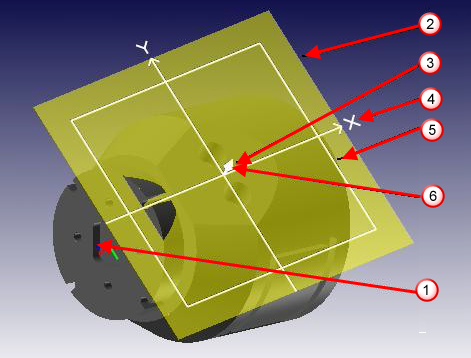
 Part Coordinate System (PCS) — A solid model imported into PartMaker uses a coordinate system called Part Coordinate System. This is a global coordinate system that does not change within a job. The Part Coordinate System is displayed in red, green and blue, denoting the Part X, Part Y and Part Z axes.
 Face Plane — The Face Plane of a given 2D Face window is the corresponding plane in the 3D Part Coordinate System containing the same two axes as the 2D Face window coordinate system. The Face Plane is displayed as a semi-transparent rectangle on the solid model.
 Face Origin — This is the intersection point of the two axes of the Face Plane. It corresponds to the Zero Point used for programming in the Face window.
 Face Coordinate System (FCS) — The Face Coordinate System of a given Face window is the 3D coordinate system consisting of the two axes of the Face Plane and the third axis perpendicular to the Face Plane and passing through the Face Origin. The Face Coordinate System Axes are displayed in white on the solid model.
 Face Boundaries — The boundary of the Face window is displayed on the solid model as a rectangle for box stock and as a circle for cylindrical stock. For cylindrical faces; that is, Mill Cylinder and Mill Diameter Face windows, the boundary is displayed as a rectangle if the face plane view is set to unwrapped, and as a cylindrical outline if the face plane view is set to wrapped.
 Machining Side Arrow — This denotes the side of the Face Plane from which machining is done. It is displayed as a white arrow rendered on the Face Origin.
You can set the Face Plane, Face Boundaries and Face Origin directly using the Define Face Plane dialog. When these are set, you can transfer geometry from the solid model into the current Face window or project geometry from the solid model onto the current Face Plane. PartMaker always transfers and projects planar geometry in a direction normal to the Face Plane.
You can also indirectly define the Face Plane, Face Boundaries and Face Origin in the following ways:
- Transferring planar geometry for planar faces through the Planar Surface Info dialog.
- Transferring unwrapped geometry through the Cylindrical Surface Info dialog for Mill Cylinder Face windows.
- Transferring holes and slots through the Cylindrical Surface Info dialog for Mill Diameter Index Face windows.
- Projecting outlines through the Surface Info dialog.