
The top-most table solid is the solid that the stock and clamps are attached to. That is, the stock and clamps in the machine simulation move around with the solid that is specified in this dialog as if they were children of the solid.
For a lathe, this is the main spindle or chuck. For mills, it is the top table solid. Use the Top-most Table dialog to set this up.
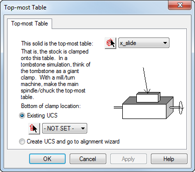
To open the Top-most Table dialog, select Machine Design tab > Configuration panel > Topmost Table.
To use this dialog:
- Select or pick the solid.
- Select either:
- Existing UCS — Select or pick the UCS on the top of the solid where you want the part mounted.
Note: If your part has its coordinate system located on its top, you can offset the solid in the Simulation Information page of the Setup wizard.
- Create UCS and go to alignment wizard
- Existing UCS — Select or pick the UCS on the top of the solid where you want the part mounted.
- Click the Apply button.
UCS for top-most table
The Top-most Table UCS is the most crucial UCS to get right, particularly for a turning machine. Both the position and the orientation of the top-most table UCS are important because they establish a correspondence to the Setup position and orientation used in the FeatureCAM part. This can be understood in several ways:
- The top-most table UCS is mated to the Setup's origin (minus the offsets in the Setup - Simulation Information dialog).
- The origins of the Setup UCS (minus the offsets in the Setup - Simulation Information dialog) are made to be coincident with the top-table UCS; and the X, Y, and Z directions are aligned.
- FeatureCAM's simulation aligns (transforms) the whole machine so that the top table UCS is aligned with the setup (minus the offsets in the Setup - Simulation Information dialog). That is, the machine is transformed such that the +X of the top table UCS is aligned to the Setup's +X, +Z to +Z, and the machine is translated such that the Setup's origin (minus the offsets in the Setup - Simulation Information dialog) is the same point as the top-table UCS origin.
Below is a sample of the UCS and solid used for a milling machine:
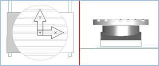
The UCS for milling should have:
- the XY positioned in the center of the table
- the Z positioned on the top of the table
- X pointing to the right
- Z pointing up
For 4-axis indexed parts, the combination of the .fm's Setup's clamp location and the top-most table location should translate the stock such that the index axis of the part is aligned with the table's rotation axis. If this is not true, the simulation cannot rotate the machine about the index axis.
Below is a sample of the UCS and solid used for a turning or turn/mill machine:
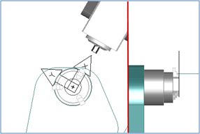
The UCS for turning should have:
- the XY positioned in the center of the chuck
- the Z positioned on the face of the jaws
- X pointing up (or towards the tool on a slant-bed lathe)
- Z pointing to the right (from the main to the sub-spindle or tailstock)