Define Connectors
Define connectors to help assemble components on the factory floor.
Connectors allow snapping between specific points on each component and aligning them based on the axes of the connector points. Connector points may be created on the following:
- A planar face
- A vertex
- A midpoint
- An endpoint
- A hole center
- A work point
Place connectors in a model
On the ribbon, click Asset Builder tab > Author panel > Define Connector
 .
.Select a planar face, vertex, midpoint, endpoint, hole center, or work point on the component. The connector point triad appears on the point you select.
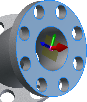
- The red axis on the triad represents the X direction for the object as seen from the plan view (looking down from the top). This is the direction in which the connection is to be made.
- The green axis indicates the side of the connection.
- The blue axis indicates the top, or up, side of the connection.
Optional: To specify a different connector point, click the origin ball of the triad and select a new location.
Optional: To align the X direction with an existing edge or face, click the red axis on the triad and then select a face or edge to align with.
Optional: To flip the triad axis, right-click anywhere on the red arrow and select Flip axis from the pop-up context menu. Flipping the triad changes the direction in which the connection is to be made. You can also flip the axis by clicking the red arrow once to highlight it, and then clicking it a second time to change the direction.
To create the connector point and complete the command, right-click anywhere on the triad or in the graphics window and select OK from the context menu. The connector point displays as a green sphere. You can also assign custom colors to your connectors.
Continue to create more connector points, as necessary.
Assign a custom color to connectors
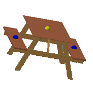
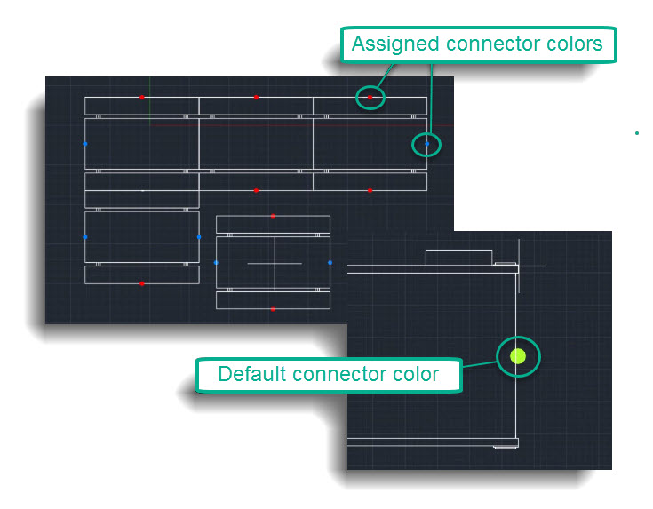
Assigning a custom color to connectors allows you to quickly identify and match connections between assets in your factory layout when placing assets.
Once you have placed and defined your asset connectors, you can then assign a custom color to those connectors from the Inventor Model browser.
Assign a color
In the Inventor Model browser, right click on the connector to expose a list of context menu options.
Expand the Factory menu options and select Assign Color.

Select a color from the Color palette to assign to your connector. The default connector color is green.
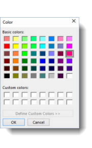
Click OK.
Save to publish the asset to the Asset Browser.
To delete a connector, right click on the connector in the Inventor Model browser and select Delete from the context menu.
Customized connector colors persist throughout future sessions. In AutoCAD Factory, these custom asset connector colors display when you go to place or connect the asset in your layout.
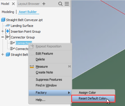
Reset Connector Color
In order to restore a connector to universal green color, you don't have to go back inside the color selection dialog to pick the correct green color. Instead, you can reset it to the default color in the context menu.
In the Inventor Model browser, right click on the connector to expose a list of context menu options.
Expand the Factory menu options and select Reset Default Color.