Running a simulation produces the FEA results for all the combinations of the defined variables. Before you run a simulation, complete all of the steps to define the parameters for the analysis.
- On the ribbon, click
Stress Analysis tab
 Solve panel
Simulate
Solve panel
Simulate
 .
.
or
In the Simulation Browser, right-click the Simulation node and select Simulate.
To run batch simulations, select multiple simulations in the browser, right-click the selection, and click Simulate.
- In the Simulate dialog box, expand the More section to see if there are any notifications or warnings that relate to process.
- When ready to start the simulation calculations, click Run.
- View the results, and enter changes to refine the design. Changes can include adding features or suppressing problematic ones.
- Sometimes changes in parameters causes Mesh and Results to become out-of-date, and an icon
 displays next to the browser node. To update mesh and results:
- To re-evaluate all existing data points, right-click the Mesh node, and click Mesh View.
- Specify the simulation method for parametric geometry:
Exhaustive set of configurations Solves all combinations of the parameters.
Smart set of configurations Solves the base configuration and each parameter change to the base, then interpolates the other results.
Current configuration only Solves the current configuration as a single point simulation.
- Rerun the simulation to update the results.
- To ensure the most accurate results, use result convergence and resolve. Result convergence is blocked for multiple-time step support and prestressed modal results.
- Repeat the process until you optimize the component.
- Create reports based on the optimal results.
To cancel the simulation in process, click Cancel or ESC .
View the log file
After you run a simulation, in the browser, right-click the Results node, and click Simulation log.
The log displays information about the simulation, and provides a link to the folder where the log file is located. You can copy and clear the log file.
Edit a design and rerun analysis
After you run an analysis on your model, you can change the design and rerun the analysis to see the effects of the changes.
- In the browser, right-click the part or assembly you want to edit, and click Open.
The component opens in another window where you can change it. At the bottom of the window near the status bar, a tab is available for each open document. This procedure includes a part edit.
- In the browser, expand the feature node that you want to edit.
- Right-click the feature that you want to edit, and click Show Dimensions.
- Double-click the dimension that you want to change, enter the new value, and then click the green check mark. The sketch updates.
- In the Quick Access Toolbar (QAT), click Update model.
- At the bottom of the window, click the assembly tab. Your component is updated.
- Some portions of the simulation can now be out of date with the change. If an update is necessary to have current analysis data, right-click the Contacts node, and click Update.
If a feature moves as a result of the geometry change when you update the simulation, the associated load glyphs relocate. The direction of the load does not change, even if the feature associated with the load changes orientation.
- Repeat step 7 for each area that requires it. Then click Simulate to update the results.
Workflow for static stress analysis
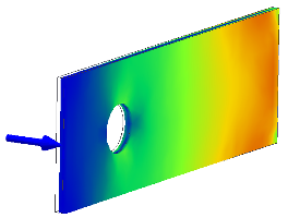
Analyze a model under different conditions using various materials, loads, and constraints (also called boundary conditions), and then view the results and evaluate different options.
- In the Stress Analysis environment, start a new simulation, and specify the simulation type Static Stress Analysis.
- Exclude components not required for simulation.
- Assign materials. If you define a modal simulation, you can run it now. There is enough information to see the natural frequencies.
- Add Constraints.
- Add Loads.
- Specify contact conditions, an optional step.
- Specify and preview the mesh, an optional step.
- Run the simulation.
- View and Interpret the Results.
Post-processing creates graphical displays that show the distribution of stresses, deformations, and other aspects of the model. After you view and evaluate the results, you can change your model and rerun the analysis to see the effect your changes produce.
When you modify the model or various inputs for the simulation, it can be necessary to update the mesh or other analysis parameters. A red lightning bolt icon next to the browser node indicates areas that need an update. Right-click the node and click Update to make them current with the modifications. For the Results node, run the Simulate command to update results.
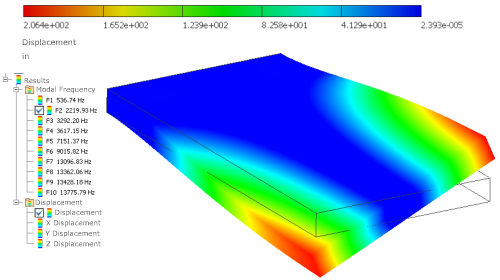
Run a modal frequency analysis
Run a modal frequency analysis separately to find the natural frequencies at which your part vibrates, and the mode shapes at those frequencies. Run a frequency analysis on a prestressed structure, where you define loads for the analysis, or to find the natural frequencies of an unconstrained model.
- In the Stress Analysis environment, start a new simulation, and specify the simulation type Modal Analysis.
- Verify that the material used for the part is suitable, or override it with appropriate materials.
- Apply the necessary constraints (optional).
- Apply any loads (optional).
- Adjust the mesh settings, and preview the mesh (optional).
- Click Simulate and in the dialog box, click Run.
In the browser, the results for the first eight frequency modes are inserted under the Results folder. For an unconstrained part, the first six frequencies are essentially zero.
- To change the number of frequencies displayed, right-click the Simulation node (near the top of the browser), and click Edit Simulation Properties.
In the dialog box, specify the number of modes to find.
- After you complete all of the required steps, the Update notification displays in the browser beside those sections that need updates. Right-click the node and click Update. On the Results node, right-click the node and click Simulate.
In the results display, the contours represent relative deformation of the part as it vibrates.
View deformation of a part at a particular frequency
- In the stress analysis browser, under Results, expand the Modal Frequency subfolder.
- Double-click the frequency that you want to see in the graphics region.